Another certificate management post as Lets Encrypt have removed their old root certificates. This post shows how to update signed certificates for NSX-T.
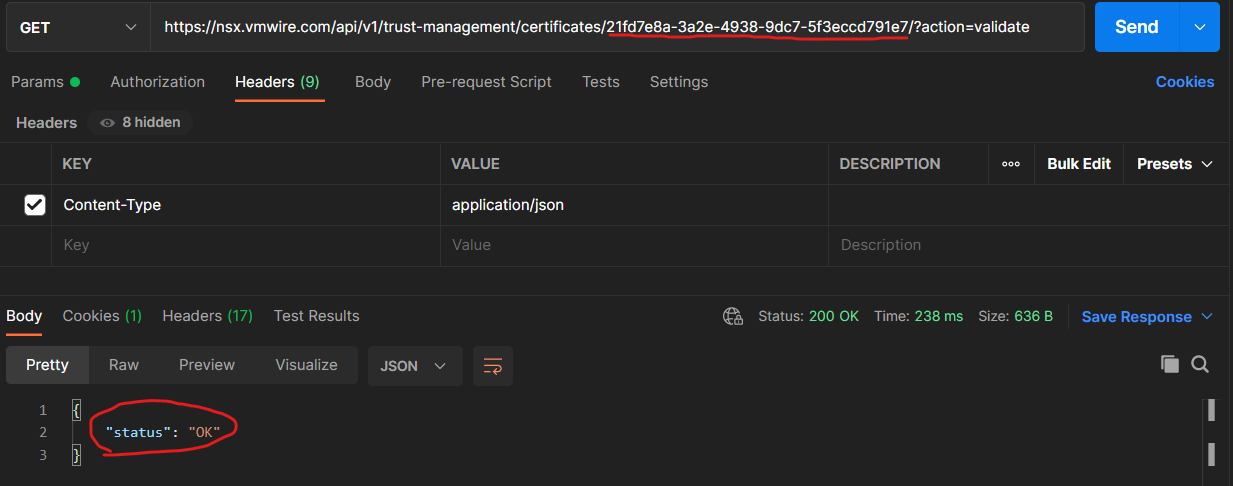
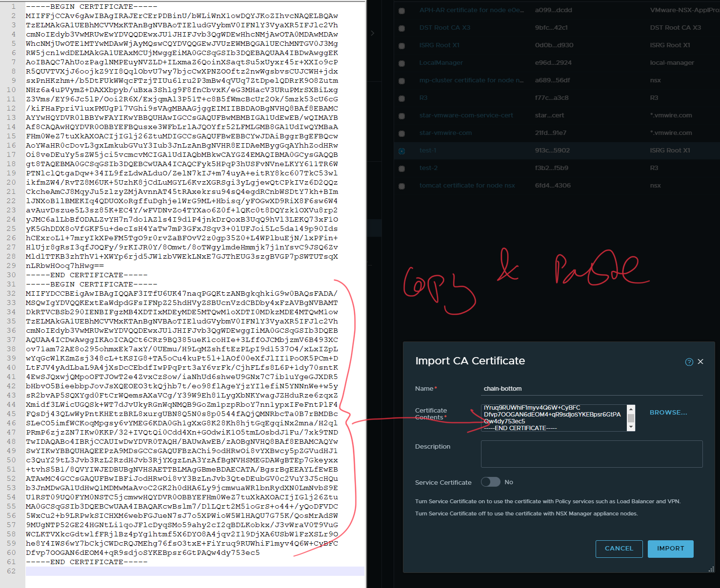
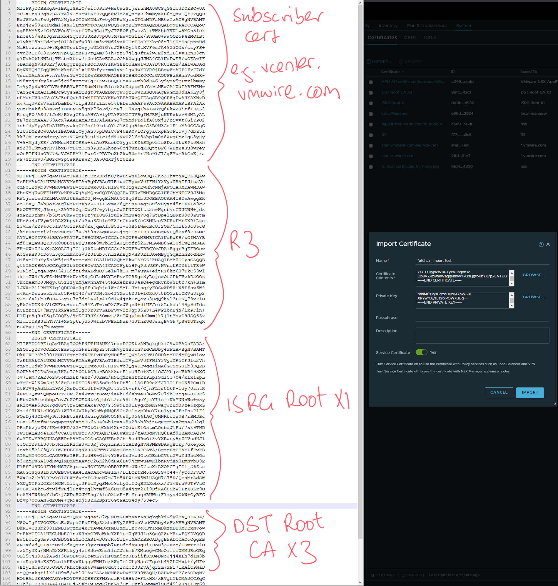
NSX-T checks certificate chains when importing certificates, and unless the full chain of trust is available, you will not be able to use the certificate with NSX-T.
Another certificate management post as Lets Encrypt have removed their old root certificates. This post shows how to update signed certificates for NSX-T.
NSX-T checks certificate chains when importing certificates, and unless the full chain of trust is available, you will not be able to use the certificate with NSX-T.
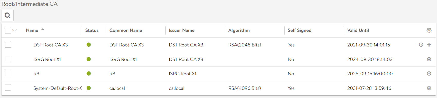
This link here shows the chain of trust for Lets Encrypt certificates.
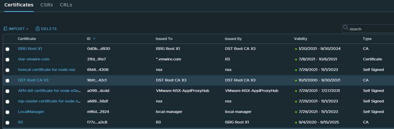
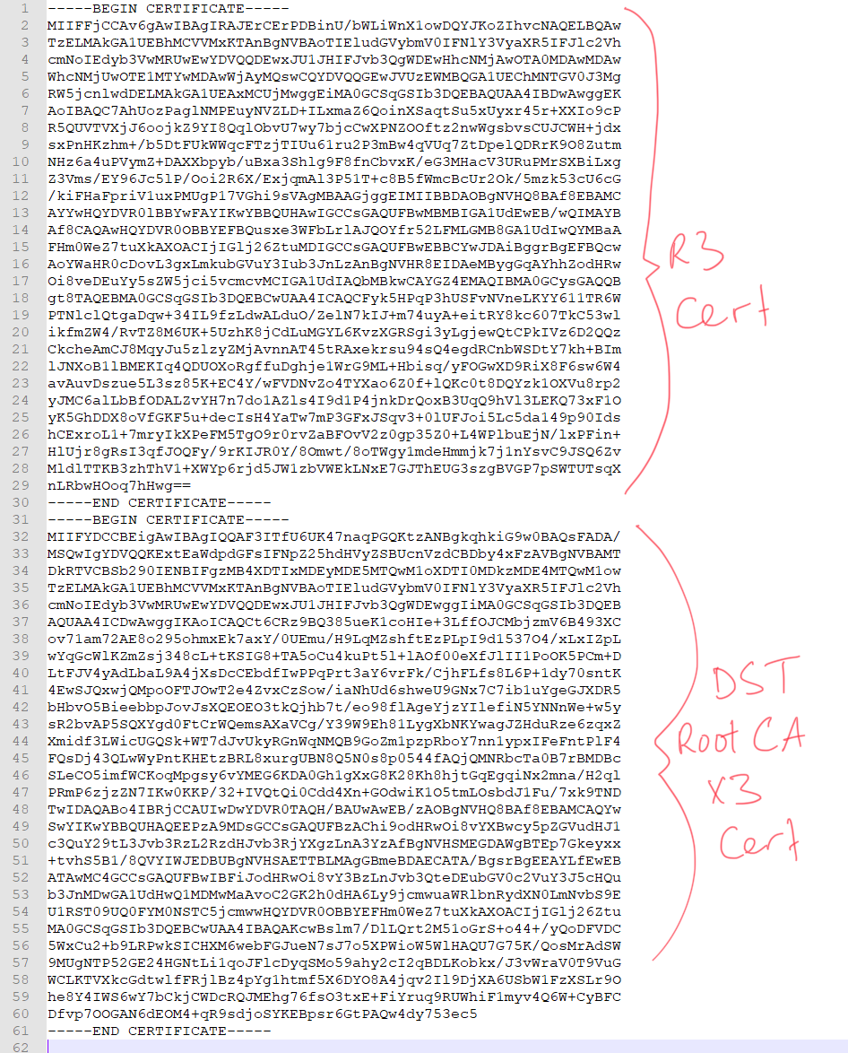
The certificate chain for Lets Encrypt is as follows:
your-certificate -> R3 -> ISRG Root X1
Your certificate is delivered to you after you request a certificate using Lets Encrypt services, the file that contains your certificate is named cert.pem.
The R3 certificate can be downloaded with this link
Now, you can release the node from that certificate by first logging into one of your NSX-T controller nodes, this only works from the node directly and not from the API.
Log into a Controller node as admin, then type st e, enter the admin password and you should be at the shell.
Post this command to release the certificate from that node.
This article describes how to setup vCenter, VCD, NSX-T and NSX Advanced Load Balancer to support exposing Kubernetes applications in Kubernetes clusters provisioned into VCD.
At the end of this post, you would be able to run this command:
… and have NSX ALB together with VCD and NSX-T automate the provisioning and setup of everything that allows you to expose that application to the outside world using a Kubernetes service of type LoadBalancer.
Create a Content Library for NSX ALB
In vCenter (Resource vCenter managing VCD PVDCs), create a Content Library for NSX Advanced Load Balancer to use to upload the service engine ova.
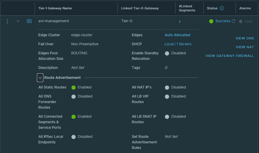
Create T1 for Avi Service Engine management network
Create T1 for Avi Service Engine management network. You can either attach this T1 to the default T0 or create a new T0.
enable DHCP server for the T1
enable All Static Routes and All Connected Segments & Service Ports under Route Advertisement
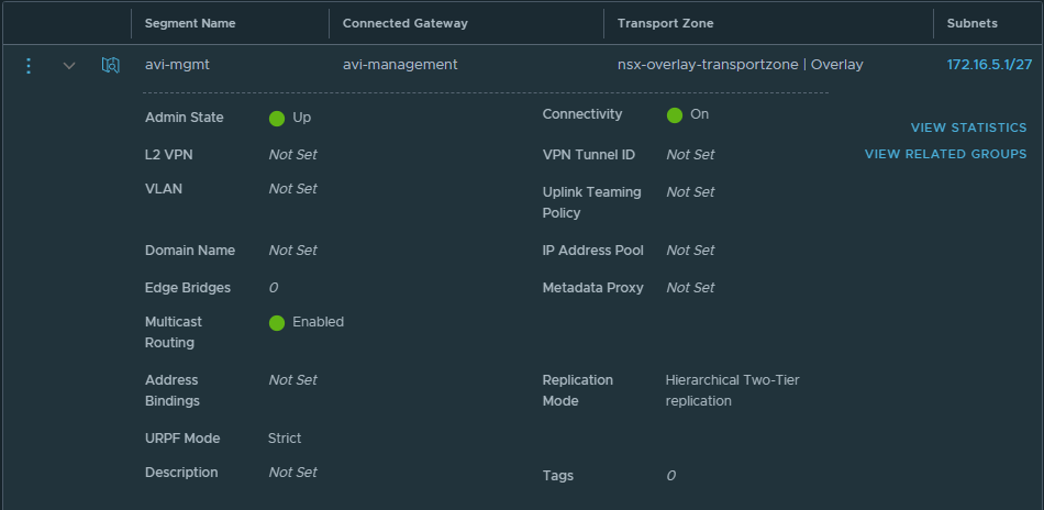
Create a network segment for Service Engine management network
Create a network segment for Avi Service Engine management network. Attach the segment to the T1 the was created in the previous step.
Ensure you enable DHCP, this will assign IP addresses to the service engines automatically and you won’t need to setup IPAM profiles in Avi Vantage.
NSX Advanced Load Balancer Settings
A couple of things to setup here.
You do not need to create any tenants in NSX ALB, just use the default admin context.
No IPAM/DNS Profiles are required as we will use DHCP from NSX-T for all networks.
Use FQDNs instead of IP addresses
Use the same FQDN in all systems for consistency and to ensure that registration between the systems work
NSX ALB
VCD
NSX-T
Navigate to Administration, User Credentials and setup user credentials for NSX-T controller and vCenter server
Navigate to Administration, Settings, Tenant Settings and ensure that the settings are as follows
Setup an NSX-T Cloud
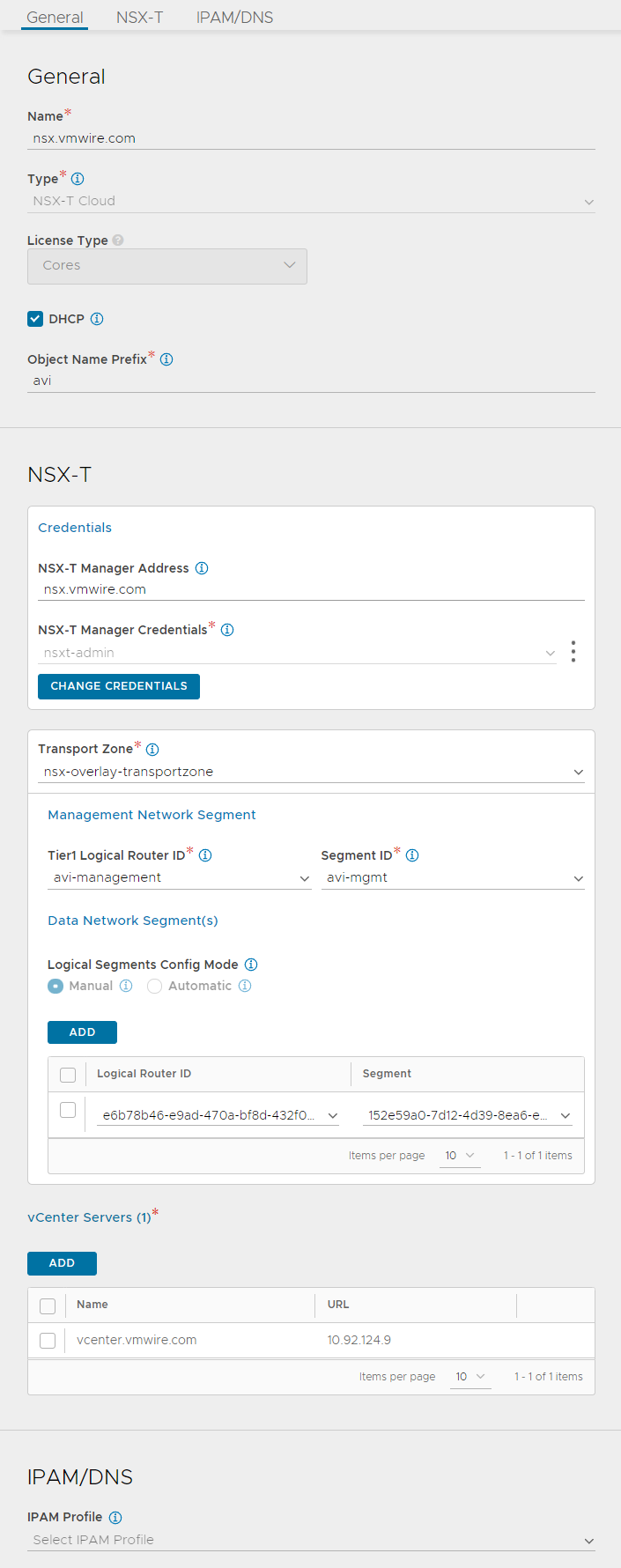
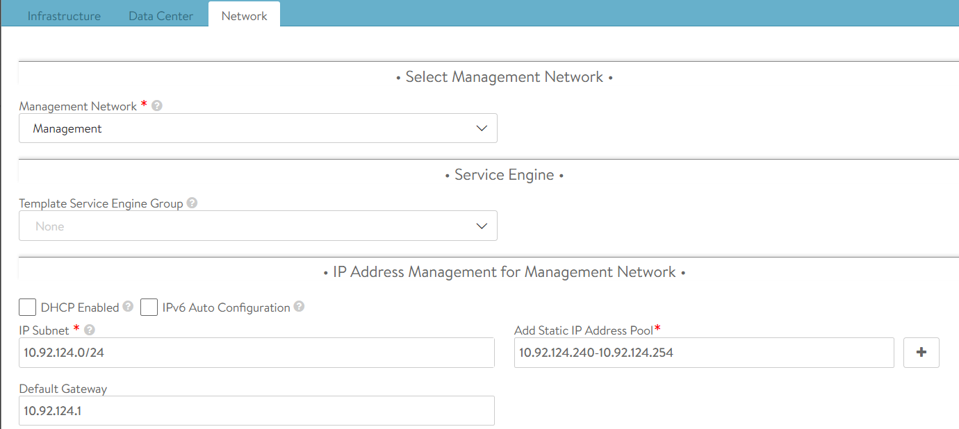
Navigate to Infrastructure, Clouds. Setup your cloud similar to mine, I have valled my NSX-T cloud nsx.vmwire.com (which is the FQDN of my NSX-T Controller).
Lets go through these settings from the top.
use the FQDN of your NSX-T manager for the name
click the DHCP option, we will be using NSX-T’s DHCP server so we can ignore IPAM/DNS later
enter something for the Object Name Prefix, this will give the SE VM name a prefix so they can be identified in vCenter. I used avi here, so it will look like this in vCenter
type the FQDN of the NSX-T manager into the NSX-T Manager Address
choose the NSX-T Manager Credentials that you configured earlier
select the Transport Zone that you are using in VCD for your tenants
under Management Network Segment, select the T1 that you created earlier for SE management networking
under Segment ID, select the network segment that you created earlier for the SE management network
click ADD under the Data Network Segment(s)
select the T1 that is used by the tenant in VCD
select the tenant organization routed network that is attached to the t1 in the previous task
the two previous settings tell NSX ALB where to place the data/vip network for front-end load balancing use. NSX-ALB will create a new segment for this in NSX-T automatically, and VCD will automatically create DNAT rules when a virtual service is requested in NSX ALB
the last step is to add the vCenter server, this would be the vCenter server that is managing the PVDCs used in VCD.
Now wait for a while until the status icon turns green and shows Complete.
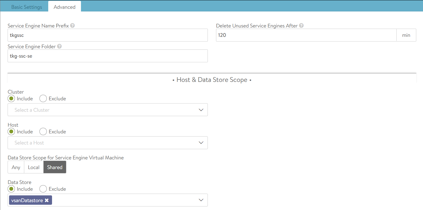
Setup a Service Engine Group
Decide whether you want to use a shared service engine group for all VCD tenants or dedicated a service engine group for each Tenant.
I use the dedicated model.
navigate to Infrastructure, Service Engine Group
change the cloud to the NSX-T cloud that you setup earlier
create a new service engine group with your preferred settings, you can read about the options here.
Setup Avi in VCD
Log into VCD as a Provider and navigate to Resources, Infrastructure Resources, NSX-ALB, Controllers and click on the ADD link.
Wait for a while for Avi to sync with VCD. Then continue to add the NSX-T Cloud.
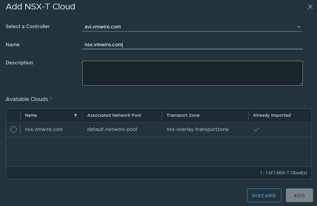
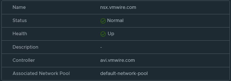
Navigate to Resources, Infrastructure Resources, NSX-ALB, NSX-T Clouds and click on the ADD link.
Proceed when you can see the status is healthy.
Navigate to Resources, Infrastructure Resources, NSX-ALB, Service Engine Groups and click on the ADD link.
Staying logged in as a Provider, navigate to the tenant that you wish to enable NSX ALB load balancing services and navigate to Networking, Edge Gateways, Load Balancer, Service Engine Groups. Then add the service engine group to this tenant.
This will enable this tenant to use NSX ALB load balancing services.
Deploy a new Kubernetes cluster in VCD with Container Service Extension
Deploy a new Kubernetes cluster using Container Service Extension in VCD as normal.
Once the cluster is ready, download the kube config file and log into the cluster.
Check that all the nodes and pods are up as normal.
You might see that the following pods in the kube-system namespace are in a pending state. If everything is already working then move onto the next section.
Wait for the load balancer service to start and the pod to go into a running state. During this time, you’ll see the service engines being provisioned automatically by NSX ALB. It’ll take 10 minutes or so to get everything up and running.
You can use this command to check when the load balancer service has completed and check the EXTERNAL-IP.
kubectl get service webserver
NAME TYPE CLUSTER-IP EXTERNAL-IP PORT(S) AGE
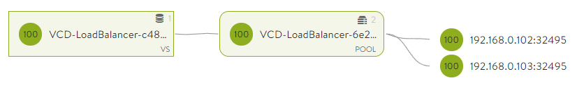
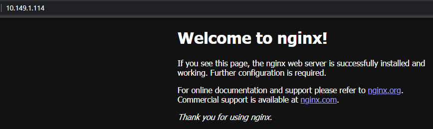
webserver LoadBalancer 100.71.45.194 10.149.1.114 80:32495/TCP 7h48m
You can see that NSX ALB, VCD and NSX-T all worked together to expose the nginx applicationto the outside world.
The external IP of 10.149.1.114 in my environment is an uplink segment on a T0 that I have configured for VCD tenants to use as egress and ingress into their organization VDC. It is the external network for their VDCs.
Paste the external IP into a web browser and you should see the nginx web page.
In the next post, I’ll go over the end to end network flow to show how this all connects NSX ALB, VCD, NSX-T and Kubernetes together.
Container Service Extension (CSE) 3.1.1 now supports persistent volumes that are backed by VCD’s Named Disk feature.
Setting up the VCD CSI driver on your Kubernetes cluster
Container Service Extension (CSE) 3.1.1 now supports persistent volumes that are backed by VCD’s Named Disk feature. These now appear under Storage – Named disks in VCD. To use this functionality today (28 September 2021), you’ll need to deploy CSE 3.1.1 beta with VCD 10.3. See this previous post for details.
Ideally, you want to deploy the CSI driver using the same user that also deployed the Kubernetes cluster into VCD. In my environment, I used a user named tenant1-admin, this user has the Organization Administrator role with the added right:
Compute – Organization VDC – Create a Shared Disk.
Create the vcloud-basic-auth.yaml
Before you can create persistent volumes you have to setup the Kubernetes cluster with the VCD CSI driver.
Ensure you can log into the cluster by downloading the kube config and logging into it using the correct context.
kubectl config get-contexts
CURRENT   NAME                          CLUSTER      AUTHINFO           NAMESPACE
*         kubernetes-admin@kubernetes   kubernetes   kubernetes-admin
Create the vcloud-basic-auth.yaml file which is used to setup the VCD CSI driver for this Kubernetes cluster.
Notice that the storageProfile needs to be set to either “*” for any storage policy or the name of a storage policy that you has access to in your Organization VDC.
Create the storage class by applying that file.
kubectl apply -f storage-class.yaml
You can see if that was successful by getting all storage classes.
kubectl get storageclass
NAME           PROVISIONER                                RECLAIMPOLICY   VOLUMEBINDINGMODE   ALLOWVOLUMEEXPANSION   AGE
vcd-disk-dev   named-disk.csi.cloud-director.vmware.com   Delete          Immediate           false                  43h
Now that we’ve got a storage class and the driver installed, we can now deploy a persistent volume claim and attach it to a pod. Lets create a persistent volume claim first.
Creating a persistent volume claim
We will need to prepare another file, I’ve called my my-pvc.yaml, and it looks like this.
kubectl get pvc
NAME     STATUS   VOLUME                                     CAPACITY   ACCESS MODES   STORAGECLASS   AGE
my-pvc   Bound    pvc-2ddeccd0-e092-4aca-a090-dff9694e2f04   1Gi        RWO            vcd-disk-dev   36m
Attaching the persistent volume to a pod
Lets deploy an nginx pod that will attach the PV and use it for nginx.
You can see that the persistentVolumeClaim, claimName: my-pvc, this aligns to the name of the PVC. I’ve also mounted it to /usr/share/nginx/html within the nginx pod.
Lets attach the PV.
kubectl apply -f pod.yaml
You’ll see a few things happen in the Recent Tasks pane when you run this. You can see that Kubernetes has attached the PV to the nginx pod using the CSI driver, the driver informs VCD to attach the disk to the worker node.
If you open up vSphere Web Client, you can see that the disk is now attached to the worker node.
You can also see the CSI driver doing its thing if you take a look at the logs with this command.
You can log into the nginx pod using this command.
kubectl exec -it pod -- bash
Then type mount and df to see the mount is present and the size of the mount point.
df
Filesystem     1K-blocks    Used Available Use% Mounted on
/dev/sdb          999320    1288    929220   1% /usr/share/nginx/html

mount
/dev/sdb on /usr/share/nginx/html type ext4 (rw,relatime)
The size is correct, being 1GB and the disk is mounted.
Describing the pod gives us more information.
kubectl describe po pod
Name:         pod
Namespace:    default
Priority:     0
Node:         node-xgsw/192.168.0.101
Start Time:   Sun, 26 Sep 2021 12:43:15 +0300
Labels:       app=nginx
Annotations:  <none>
Status:       Running
IP:           100.96.1.12
IPs:
  IP:  100.96.1.12
Containers:
  my-pod-container:
    Container ID:   containerd://6a194ac30dab7dc5a5127180af139e531e650bedbb140e4dc378c21869bd570f
    Image:          nginx
    Image ID:       docker.io/library/nginx@sha256:853b221d3341add7aaadf5f81dd088ea943ab9c918766e295321294b035f3f3e
    Port:           80/TCP
    Host Port:      0/TCP
    State:          Running
      Started:      Sun, 26 Sep 2021 12:43:34 +0300
    Ready:          True
    Restart Count:  0
    Environment:    <none>
    Mounts:
      /usr/share/nginx/html from my-pod-storage (rw)
      /var/run/secrets/kubernetes.io/serviceaccount from default-token-xm4gd (ro)
Conditions:
  Type              Status
  Initialized       True
  Ready             True
  ContainersReady   True
  PodScheduled      True
Volumes:
  my-pod-storage:
    Type:       PersistentVolumeClaim (a reference to a PersistentVolumeClaim in the same namespace)
    ClaimName:  my-pvc
    ReadOnly:   false
  default-token-xm4gd:
    Type:        Secret (a volume populated by a Secret)
    SecretName:  default-token-xm4gd
    Optional:    false
QoS Class:       BestEffort
Node-Selectors:  <none>
Tolerations:     node.kubernetes.io/not-ready:NoExecute op=Exists for 300s
                 node.kubernetes.io/unreachable:NoExecute op=Exists for 300s
Events:          <none>
Useful commands
Show storage classes
kubectl get storageclass
Show persistent volumes and persistent volume claims
Photon OS 3 does not support Linux guest customization unfortunately, so we will use the links below to manually setup the OS with a hostname and static IP address.
Boot the VM, the default credentials are root with password changeme. Change the default password.
Photon 3 has the older repositories, so we will need to update to newer repositories as detailed in this KB article. I’ve included this in the instructions below.
Copypasta or use create a bash script.
# Update Photon repositories
cd /etc/yum.repos.d/
sed -i 's/dl.bintray.com\/vmware/packages.vmware.com\/photon\/$releasever/g' photon.repo photon-updates.repo photon-extras.repo photon-debuginfo.repo
# Update Photon
tdnf --assumeyes update
# Install dependencies
tdnf --assumeyes install build-essential python3-devel python3-pip git
# Prepare cse user and application directories
mkdir -p /opt/vmware/cse
chmod 775 -R /opt
chmod 777 /
groupadd cse
useradd cse -g cse -m -p Vmware1! -d /opt/vmware/cse
chown cse:cse -R /opt
# Run as cse user
su - cse
mkdir -p ~/.ssh
cat >> ~/.ssh/authorized_keys << EOF
ssh-rsa AAAAB3NzaC1yc2EAAAABJQAAAQEAhcw67bz3xRjyhPLysMhUHJPhmatJkmPUdMUEZre+MeiDhC602jkRUNVu43Nk8iD/I07kLxdAdVPZNoZuWE7WBjmn13xf0Ki2hSH/47z3ObXrd8Vleq0CXa+qRnCeYM3FiKb4D5IfL4XkHW83qwp8PuX8FHJrXY8RacVaOWXrESCnl3cSC0tA3eVxWoJ1kwHxhSTfJ9xBtKyCqkoulqyqFYU2A1oMazaK9TYWKmtcYRn27CC1Jrwawt2zfbNsQbHx1jlDoIO6FLz8Dfkm0DToanw0GoHs2Q+uXJ8ve/oBs0VJZFYPquBmcyfny4WIh4L0lwzsiAVWJ6PvzF5HMuNcwQ== rsa-key-20210508
EOF
cat >> ~/.bash_profile << EOF
# For Container Service Extension
export CSE_CONFIG=/opt/vmware/cse/config/config.yaml
export CSE_CONFIG_PASSWORD=Vmware1!
source /opt/vmware/cse/python/bin/activate
EOF
# Install CSE in virtual environment
python3 -m venv /opt/vmware/cse/python
source /opt/vmware/cse/python/bin/activate
pip3 install git+https://github.com/vmware/container-service-extension.git@3.1.1.0b2
cse version
source ~/.bash_profile
# Prepare vcd-cli
mkdir -p ~/.vcd-cli
cat > ~/.vcd-cli/profiles.yaml << EOF
extensions:
- container_service_extension.client.cse
EOF
vcd cse version
# Add my Let's Encrypt intermediate and root certs. Use your certificates issued by your CA to enable verify=true with CSE.
cat >> /opt/vmware/cse/python/lib/python3.7/site-packages/certifi/cacert.pem << EOF #ok
-----BEGIN CERTIFICATE-----
MIIFFjCCAv6gAwIBAgIRAJErCErPDBinU/bWLiWnX1owDQYJKoZIhvcNAQELBQAw
TzELMAkGA1UEBhMCVVMxKTAnBgNVBAoTIEludGVybmV0IFNlY3VyaXR5IFJlc2Vh
cmNoIEdyb3VwMRUwEwYDVQQDEwxJU1JHIFJvb3QgWDEwHhcNMjAwOTA0MDAwMDAw
WhcNMjUwOTE1MTYwMDAwWjAyMQswCQYDVQQGEwJVUzEWMBQGA1UEChMNTGV0J3Mg
RW5jcnlwdDELMAkGA1UEAxMCUjMwggEiMA0GCSqGSIb3DQEBAQUAA4IBDwAwggEK
AoIBAQC7AhUozPaglNMPEuyNVZLD+ILxmaZ6QoinXSaqtSu5xUyxr45r+XXIo9cP
R5QUVTVXjJ6oojkZ9YI8QqlObvU7wy7bjcCwXPNZOOftz2nwWgsbvsCUJCWH+jdx
sxPnHKzhm+/b5DtFUkWWqcFTzjTIUu61ru2P3mBw4qVUq7ZtDpelQDRrK9O8Zutm
NHz6a4uPVymZ+DAXXbpyb/uBxa3Shlg9F8fnCbvxK/eG3MHacV3URuPMrSXBiLxg
Z3Vms/EY96Jc5lP/Ooi2R6X/ExjqmAl3P51T+c8B5fWmcBcUr2Ok/5mzk53cU6cG
/kiFHaFpriV1uxPMUgP17VGhi9sVAgMBAAGjggEIMIIBBDAOBgNVHQ8BAf8EBAMC
AYYwHQYDVR0lBBYwFAYIKwYBBQUHAwIGCCsGAQUFBwMBMBIGA1UdEwEB/wQIMAYB
Af8CAQAwHQYDVR0OBBYEFBQusxe3WFbLrlAJQOYfr52LFMLGMB8GA1UdIwQYMBaA
FHm0WeZ7tuXkAXOACIjIGlj26ZtuMDIGCCsGAQUFBwEBBCYwJDAiBggrBgEFBQcw
AoYWaHR0cDovL3gxLmkubGVuY3Iub3JnLzAnBgNVHR8EIDAeMBygGqAYhhZodHRw
Oi8veDEuYy5sZW5jci5vcmcvMCIGA1UdIAQbMBkwCAYGZ4EMAQIBMA0GCysGAQQB
gt8TAQEBMA0GCSqGSIb3DQEBCwUAA4ICAQCFyk5HPqP3hUSFvNVneLKYY611TR6W
PTNlclQtgaDqw+34IL9fzLdwALduO/ZelN7kIJ+m74uyA+eitRY8kc607TkC53wl
ikfmZW4/RvTZ8M6UK+5UzhK8jCdLuMGYL6KvzXGRSgi3yLgjewQtCPkIVz6D2QQz
CkcheAmCJ8MqyJu5zlzyZMjAvnnAT45tRAxekrsu94sQ4egdRCnbWSDtY7kh+BIm
lJNXoB1lBMEKIq4QDUOXoRgffuDghje1WrG9ML+Hbisq/yFOGwXD9RiX8F6sw6W4
avAuvDszue5L3sz85K+EC4Y/wFVDNvZo4TYXao6Z0f+lQKc0t8DQYzk1OXVu8rp2
yJMC6alLbBfODALZvYH7n7do1AZls4I9d1P4jnkDrQoxB3UqQ9hVl3LEKQ73xF1O
yK5GhDDX8oVfGKF5u+decIsH4YaTw7mP3GFxJSqv3+0lUFJoi5Lc5da149p90Ids
hCExroL1+7mryIkXPeFM5TgO9r0rvZaBFOvV2z0gp35Z0+L4WPlbuEjN/lxPFin+
HlUjr8gRsI3qfJOQFy/9rKIJR0Y/8Omwt/8oTWgy1mdeHmmjk7j1nYsvC9JSQ6Zv
MldlTTKB3zhThV1+XWYp6rjd5JW1zbVWEkLNxE7GJThEUG3szgBVGP7pSWTUTsqX
nLRbwHOoq7hHwg==
-----END CERTIFICATE-----
-----BEGIN CERTIFICATE-----
MIIFYDCCBEigAwIBAgIQQAF3ITfU6UK47naqPGQKtzANBgkqhkiG9w0BAQsFADA/
MSQwIgYDVQQKExtEaWdpdGFsIFNpZ25hdHVyZSBUcnVzdCBDby4xFzAVBgNVBAMT
DkRTVCBSb290IENBIFgzMB4XDTIxMDEyMDE5MTQwM1oXDTI0MDkzMDE4MTQwM1ow
TzELMAkGA1UEBhMCVVMxKTAnBgNVBAoTIEludGVybmV0IFNlY3VyaXR5IFJlc2Vh
cmNoIEdyb3VwMRUwEwYDVQQDEwxJU1JHIFJvb3QgWDEwggIiMA0GCSqGSIb3DQEB
AQUAA4ICDwAwggIKAoICAQCt6CRz9BQ385ueK1coHIe+3LffOJCMbjzmV6B493XC
ov71am72AE8o295ohmxEk7axY/0UEmu/H9LqMZshftEzPLpI9d1537O4/xLxIZpL
wYqGcWlKZmZsj348cL+tKSIG8+TA5oCu4kuPt5l+lAOf00eXfJlII1PoOK5PCm+D
LtFJV4yAdLbaL9A4jXsDcCEbdfIwPPqPrt3aY6vrFk/CjhFLfs8L6P+1dy70sntK
4EwSJQxwjQMpoOFTJOwT2e4ZvxCzSow/iaNhUd6shweU9GNx7C7ib1uYgeGJXDR5
bHbvO5BieebbpJovJsXQEOEO3tkQjhb7t/eo98flAgeYjzYIlefiN5YNNnWe+w5y
sR2bvAP5SQXYgd0FtCrWQemsAXaVCg/Y39W9Eh81LygXbNKYwagJZHduRze6zqxZ
Xmidf3LWicUGQSk+WT7dJvUkyRGnWqNMQB9GoZm1pzpRboY7nn1ypxIFeFntPlF4
FQsDj43QLwWyPntKHEtzBRL8xurgUBN8Q5N0s8p0544fAQjQMNRbcTa0B7rBMDBc
SLeCO5imfWCKoqMpgsy6vYMEG6KDA0Gh1gXxG8K28Kh8hjtGqEgqiNx2mna/H2ql
PRmP6zjzZN7IKw0KKP/32+IVQtQi0Cdd4Xn+GOdwiK1O5tmLOsbdJ1Fu/7xk9TND
TwIDAQABo4IBRjCCAUIwDwYDVR0TAQH/BAUwAwEB/zAOBgNVHQ8BAf8EBAMCAQYw
SwYIKwYBBQUHAQEEPzA9MDsGCCsGAQUFBzAChi9odHRwOi8vYXBwcy5pZGVudHJ1
c3QuY29tL3Jvb3RzL2RzdHJvb3RjYXgzLnA3YzAfBgNVHSMEGDAWgBTEp7Gkeyxx
+tvhS5B1/8QVYIWJEDBUBgNVHSAETTBLMAgGBmeBDAECATA/BgsrBgEEAYLfEwEB
ATAwMC4GCCsGAQUFBwIBFiJodHRwOi8vY3BzLnJvb3QteDEubGV0c2VuY3J5cHQu
b3JnMDwGA1UdHwQ1MDMwMaAvoC2GK2h0dHA6Ly9jcmwuaWRlbnRydXN0LmNvbS9E
U1RST09UQ0FYM0NSTC5jcmwwHQYDVR0OBBYEFHm0WeZ7tuXkAXOACIjIGlj26Ztu
MA0GCSqGSIb3DQEBCwUAA4IBAQAKcwBslm7/DlLQrt2M51oGrS+o44+/yQoDFVDC
5WxCu2+b9LRPwkSICHXM6webFGJueN7sJ7o5XPWioW5WlHAQU7G75K/QosMrAdSW
9MUgNTP52GE24HGNtLi1qoJFlcDyqSMo59ahy2cI2qBDLKobkx/J3vWraV0T9VuG
WCLKTVXkcGdtwlfFRjlBz4pYg1htmf5X6DYO8A4jqv2Il9DjXA6USbW1FzXSLr9O
he8Y4IWS6wY7bCkjCWDcRQJMEhg76fsO3txE+FiYruq9RUWhiF1myv4Q6W+CyBFC
Dfvp7OOGAN6dEOM4+qR9sdjoSYKEBpsr6GtPAQw4dy753ec5
-----END CERTIFICATE-----
-----BEGIN CERTIFICATE-----
MIIDSjCCAjKgAwIBAgIQRK+wgNajJ7qJMDmGLvhAazANBgkqhkiG9w0BAQUFADA/
MSQwIgYDVQQKExtEaWdpdGFsIFNpZ25hdHVyZSBUcnVzdCBDby4xFzAVBgNVBAMT
DkRTVCBSb290IENBIFgzMB4XDTAwMDkzMDIxMTIxOVoXDTIxMDkzMDE0MDExNVow
PzEkMCIGA1UEChMbRGlnaXRhbCBTaWduYXR1cmUgVHJ1c3QgQ28uMRcwFQYDVQQD
Ew5EU1QgUm9vdCBDQSBYMzCCASIwDQYJKoZIhvcNAQEBBQADggEPADCCAQoCggEB
AN+v6ZdQCINXtMxiZfaQguzH0yxrMMpb7NnDfcdAwRgUi+DoM3ZJKuM/IUmTrE4O
rz5Iy2Xu/NMhD2XSKtkyj4zl93ewEnu1lcCJo6m67XMuegwGMoOifooUMM0RoOEq
OLl5CjH9UL2AZd+3UWODyOKIYepLYYHsUmu5ouJLGiifSKOeDNoJjj4XLh7dIN9b
xiqKqy69cK3FCxolkHRyxXtqqzTWMIn/5WgTe1QLyNau7Fqckh49ZLOMxt+/yUFw
7BZy1SbsOFU5Q9D8/RhcQPGX69Wam40dutolucbY38EVAjqr2m7xPi71XAicPNaD
aeQQmxkqtilX4+U9m5/wAl0CAwEAAaNCMEAwDwYDVR0TAQH/BAUwAwEB/zAOBgNV
HQ8BAf8EBAMCAQYwHQYDVR0OBBYEFMSnsaR7LHH62+FLkHX/xBVghYkQMA0GCSqG
SIb3DQEBBQUAA4IBAQCjGiybFwBcqR7uKGY3Or+Dxz9LwwmglSBd49lZRNI+DT69
ikugdB/OEIKcdBodfpga3csTS7MgROSR6cz8faXbauX+5v3gTt23ADq1cEmv8uXr
AvHRAosZy5Q6XkjEGB5YGV8eAlrwDPGxrancWYaLbumR9YbK+rlmM6pZW87ipxZz
R8srzJmwN0jP41ZL9c8PDHIyh8bwRLtTcm1D9SZImlJnt1ir/md2cXjbDaJWFBM5
JDGFoqgCWjBH4d1QB7wCCZAA62RjYJsWvIjJEubSfZGL+T0yjWW06XyxV3bqxbYo
Ob8VZRzI9neWagqNdwvYkQsEjgfbKbYK7p2CNTUQ
-----END CERTIFICATE-----
EOF
# Create service account
vcd login vcd.vmwire.com system administrator -p Vmware1!
cse create-service-role vcd.vmwire.com
# Enter system administrator username and password
# Create VCD service account for CSE
vcd user create --enabled svc-cse Vmware1! "CSE Service Role"
# Create config file
mkdir -p /opt/vmware/cse/config
cat > /opt/vmware/cse/config/config-not-encrypted.conf << EOF
mqtt:
verify_ssl: false
vcd:
host: vcd.vmwire.com
log: true
password: Vmware1!
port: 443
username: administrator
verify: true
vcs:
- name: vcenter.vmwire.com
password: Vmware1!
username: administrator@vsphere.local
verify: true
service:
enforce_authorization: false
legacy_mode: false
log_wire: false
processors: 15
telemetry:
enable: true
broker:
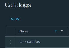
catalog: cse-catalog
ip_allocation_mode: pool
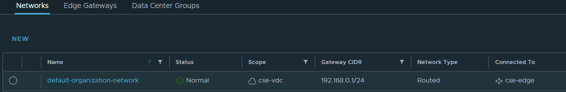
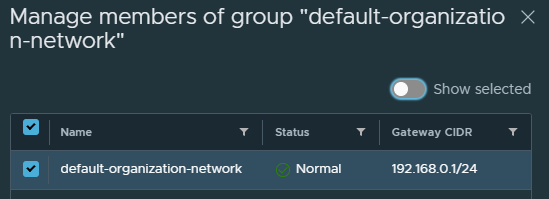
network: default-organization-network
org: cse
remote_template_cookbook_url: https://raw.githubusercontent.com/vmware/container-service-extension-templates/master/template_v2.yaml
storage_profile: 'truenas-iscsi-luns'
vdc: cse-vdc
EOF
cse encrypt /opt/vmware/cse/config/config-not-encrypted.conf --output /opt/vmware/cse/config/config.yaml
chmod 600 /opt/vmware/cse/config/config.yaml
cse check /opt/vmware/cse/config/config.yaml
cse template list
mkdir -p ~/.ssh
# Add your public key(s) here
cat >> ~/.ssh/authorized_keys << EOF
ssh-rsa AAAAB3NzaC1yc2EAAAABJQAAAQEAhcw67bz3xRjyhPLysMhUHJPhmatJkmPUdMUEZre+MeiDhC602jkRUNVu43Nk8iD/I07kLxdAdVPZNoZuWE7WBjmn13xf0Ki2hSH/47z3ObXrd8Vleq0CXa+qRnCeYM3FiKb4D5IfL4XkHW83qwp8PuX8FHJrXY8RacVaOWXrESCnl3cSC0tA3eVxWoJ1kwHxhSTfJ9xBtKyCqkoulqyqFYU2A1oMazaK9TYWKmtcYRn27CC1Jrwawt2zfbNsQbHx1jlDoIO6FLz8Dfkm0DToanw0GoHs2Q+uXJ8ve/oBs0VJZFYPquBmcyfny4WIh4L0lwzsiAVWJ6PvzF5HMuNcwQ== rsa-key-20210508
EOF
# Import TKGm ova with this command
# Copy the ova to /home/ first, the ova can be obtained from my.vmware.com, ensure that it has chmod 644 permissions.
cse template import -F /home/ubuntu-2004-kube-v1.20.5-vmware.2-tkg.1-6700972457122900687.ova
# Install CSE
cse install -k ~/.ssh/authorized_keys
# Or use this if you've already installed and want to skip template creation again
cse upgrade --skip-template-creation -k ~/.ssh/authorized_keys
# Setup cse.sh
cat > /opt/vmware/cse/cse.sh << EOF
#!/usr/bin/env bash
source /opt/vmware/cse/python/bin/activate
export CSE_CONFIG=/opt/vmware/cse/config/config.yaml
export CSE_CONFIG_PASSWORD=Vmware1!
cse run
EOF
# Make cse.sh executable
chmod +x /opt/vmware/cse/cse.sh
# Deactivate the python virtual environment and go back to root
deactivate
exit
# Setup cse.service, use MQTT and not RabbitMQ
cat > /etc/systemd/system/cse.service << EOF
[Unit]
Description=Container Service Extension for VMware Cloud Director
[Service]
ExecStart=/opt/vmware/cse/cse.sh
User=cse
WorkingDirectory=/opt/vmware/cse
Type=simple
Restart=always
[Install]
WantedBy=default.target
EOF
systemctl enable cse.service
systemctl start cse.service
systemctl status cse.service
Enable Global Roles to use CSE or Configure Rights Bundles
The quickest way to get CSE working is to add the relevant rights to the Organization Administrator role. You can create a custom rights bundle and create a custom role for the k8s admin tenant persona if you like. I won’t cover that in this post.
Log in as the /Provider and go to the Administration menu and click on Global Roles on the left.
Edit the Organization Administrator role and scroll all the way down to the bottom and click both the View 8/8 and Manage 12/12, then Save.
A quick note on the Rights Bundles for Container Service Extension when enabling native, TKGm or TKGs clusters.
The rights bundle named vmware:tkgcluster Entitlement are for TKGs clusters and NOT for TKGm.
The rights bundle named cse:nativeCluster Entitlement are for native clusters AND also for TKGm clusters.
Yes, this is very confusing and will be fixed in an upcoming release.
You can see a brief note about this on the release notes here.
Users deploying VMware Tanzu Kubernetes Grid clusters should have the rights required to deploy exposed native clusters and additionally the right Full Control: CSE:NATIVECLUSTER. This right is crucial for VCD CPI to work properly.
So in summary, for a user to be able to deploy TKGm clusters they will need to have the cse:nativeCluster Entitlement rights.
To publish these rights, go to the Provider portal and navigate to Administration, Rights Bundles.
Click on the radio button next to cse:nativeCluster Entitlement and click on Publish, then publish to the desired tenant or to all tenants.
A short post on some operational tips for CSE 3.0.4. This post covers recommendations for sizing the CSE server, how to protect it from failure, finding the important log files and other tips and tricks.
A short post on some operational tips for CSE 3.0.4. This post covers recommendations for sizing the CSE server, how to protect it from failure, finding the important log files and other tips and tricks.
Important files
Backup the following files. Its a good idea to perform image level backups of the VM too.
All file locations below assume you’re using the automated method to deploy CSE.
Contains the configuration for CSE server. Ensure you keep a safe backup of both the unecrypted file, so you can make changes and keep the encrypted file in case you lose the CSE server for whatever reason.
/opt/vmware/cse/.cse_scripts/*
Here you’ll find a bunch of directories that hold the Kubernetes templates runtimes for all of the supported Kubernetes versions.
The supported templates are the TKGm ones and the native ones.
Take a backup of this entire directory. You will need this if you want to save time when you redeploy CSE into a new VM but you’ve already prepared the templates and the templates are ready in the VCD catalog.
Saving these directories and copying them to the new CSE VM will enable you to run the command:
This will skip the long process of template creation again but allow you to setup CSE on the new VM.
If you didn’t take a backup of the .cse_scripts directory and redeployed CSE with the –skip-template-creation flag and already have the templates in catalog – when you go to deploy a Kubernetes cluster with VCD you’ll see an error such as:
FileNotFoundError: [Errno 2] No such file or directory: '/opt/vmware/cse/.cse_scripts/ubuntu-16.04_k8-1.18_weave-2.6.5_rev2/mstr.sh'
How to install both native and TKGm templates
There are two cookbooks that can be used to install CSE and enable template creation into VCD. The two are
For a really easy end to end automated deployment of both native and TKGm templates, use the bash script I developed in my GitHub repository.
Use vSphere HA for the CSE server
The CSE server can not support its own high availability through multiple VMs and sharing state. In fact, CSE is designed not to hold any state and communicates entirely with VCD through the message bus either with MQTT or RabbitMQ.
Use vSphere HA with high priority to ensure that the CSE server is started quickly in the event of a loss of an ESXi host.
The following is unsupported – I’ve tested running two CSE servers using the same config.yaml file on two separate VMs and this does in fact work without any obvious errors. Since CSE is stateless and uses a message bus to function and to provide the extension capability for container service with VCD. However this is totally unsupported by VMware GSS, so don’t do this.
This configuration will support up to 50 concurrent operations. Doubling the resource will not double the number of concurrent operations as there are many variables to consider. The bottleneck would be the ability for VCD to place messages on MQTT or RabbitMQ and also VCD’s operations concurrency.
Log files
Log file location
Why?
/opt/vmware/cse/.cse-logs/cse-server-debug.log
More detailed debug logs, use this one if something fails.
/opt/vmware/cse/.cse-logs/cse-server-info.log
CSE server logs and message bus messages
File Permissions for a healthy CSE server installation
I spent some time scratching my head with this when I wrote the bash script. The script ran as root but used sudo -u cse -i to run a Python virtual environment to install CSE as the cse user, this cause some issues initially but were resolved with the following chown and chmod settings.
File
Specification
entire /opt/vmware/cse directory
chown cse:cse -R chmod 775 -R
/opt/vmware/cse/config/config.yaml
chmod 600 chown cse:cse
/opt/vmware/cse/cse.sh
cse user execute permissions
CSE server service operations
systemctl start cse.service
Start the CSE service
systemctl stop cse.service
Stop the CSE service
systemctl status cse.service
Show current status
systemctl status cse.service ● cse.service - Container Service Extension for VMware Cloud Director Loaded: loaded (/etc/systemd/system/cse.service; enabled; vendor preset: enabled) Active: active (running) since Tue 2021-08-24 12:47:43 UTC; 7h ago Main PID: 4154 (bash) Tasks: 19 (limit: 2368) Memory: 73.6M CGroup: /system.slice/cse.service ├─4154 bash /opt/vmware/cse/cse.sh └─4155 /opt/vmware/cse/python/bin/python3 /opt/vmware/cse/python/bin/cse run
Use CA signed certificates
Use CA signed certificates for VCD, vCenter. In your production environments you should! Even in your test environments or home labs it is very easy to obtain CA signed certs to use from a provider such as Let’s Encrypt. I’ve in fact written about this in some of my previous posts. Here for vCD and here for the rest.
Using CA signed certs allows you to set the key verify to true in the config.yaml file.
verify=true
Doing so makes you CSE server much more secure. This also allows you to use the vcd and cse CLIs without using the -i -w flags which is logging in without verifying certs and to disable warnings respectively. This is of course unsafe.
In order to ensure end to end security between CSE server, VCD and vCenter, import the certificate chain consisting of the INTERMEDIATE and ROOT certs from the certificate authority into the certs store on the CSE server.
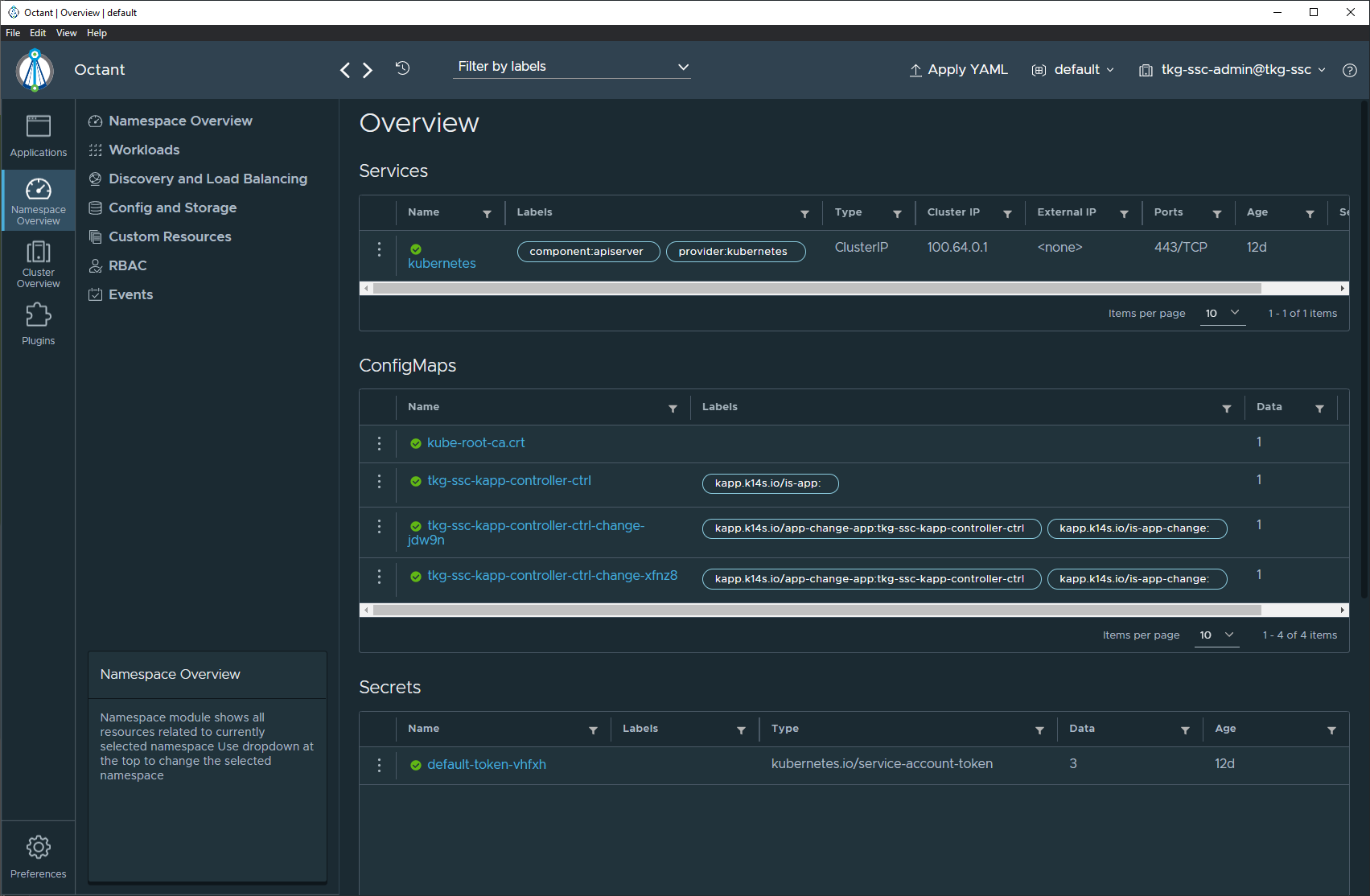
Yes, Kubernetes clusters deployed by CSE into VCD can be monitored with Octant. I wrote about it previously here.
All you need to do is update your local kubeconfig file with the kubconfig that you downloaded from CSE in VCD.
As long as the workstation where Octant is running can route to the Control Plane endpoint for the Kubernetes cluster, Octant can then see and provided you with its great dashboards. You can use the CSE expose feature for this if your workstation is not inside the VCD cloud.
Removing clusters that failed to deploy
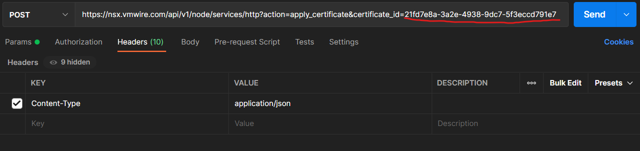
Obtain the cluster UID,
On CSE run this command to obtain the UID vcd cse cluster info, look for the uid parameter, it is all the way at the bottom, copy it to your clipboard.
Open up Postman or something with curl installed.
GET https://{{vcd_public_address}}/cloudapi/1.0.0/entities/urn:vcloud:entity:cse:nativeCluster:577b8c6c-bee4-49fb-8c03-2a22390f2783
POST https://{{vcd_public_address}}/cloudapi/1.0.0/entities/urn:vcloud:entity:cse:nativeCluster:577b8c6c-bee4-49fb-8c03-2a22390f2783/resolve
DEL https://{{vcd_public_address}}/cloudapi/1.0.0/entities/urn:vcloud:entity:cse:nativeCluster:577b8c6c-bee4-49fb-8c03-2a22390f2783
If that did not work use this DEL https://{{vcd_public_address}}/cloudapi/1.0.0/entities/urn:vcloud:entity:cse:nativeCluster:577b8c6c-bee4-49fb-8c03-2a22390f2783?invokeHooks=false
Known issues
Cannot deploy TKGm runtimes with expose set to true.
If you tried to use the exposefeature when deploying a TKGm runtime it would fail. This is a known issue with CSE 3.0.4 and is being fixed, I’ll update this post when a fix is released.
Following the previous post where I described how to install Container Service Extension 3.0.4 into Photon OS 3. This post introduces an automated method of the same thing using a bash script.
You can find the details on my github account under the repository named cse.
Following the previous post where I described how to install Container Service Extension 3.0.4 into Photon OS 3. This post introduces an automated method of the same thing using a bash script.
You can find the details on my github account under the repository named cse.
Ensure it can also reach VCD on TCP 443 and vCenter servers registered in VCD on TCP 443.
SSH into the Photon VM
Note that my environment has CA signed SSL certs and the script has been tested against this environment. I have not tested the script in environments with self-signed certificates.
Download cse-install.sh script to Photon VM
# Download the script to the Photon VM
curl https://raw.githubusercontent.com/hugopow/cse/main/cse-install.sh --output cse-install.sh
# Make script executable
chmod +x cse-install.sh
Change the cse-install.sh script
Make sure you change passwords, CA SSL certificates and environment variables to suit your environment.
In my previous post I used CentOS to run the CSE server. CentOS is unofficially dead so I thought I’d replace the CSE server with Photon instead. This guide details the steps to get CSE running on Photon 3 with a non-root user and running CSE as a Linux service.
In my previous post I used CentOS to run the CSE server. CentOS is unofficially dead so I thought I’d replace the CSE server with Photon instead. This guide details the steps to get CSE running on Photon 3 with a non-root user and running CSE as a Linux service.
Why Photon 3 and not Photon 4?
Photon OS 4 has a newer version of Python that is not supported by CSE. CSE requires Python 3.7.x which is default for Photon 3.
Photon OS 3 does not support Linux guest customization unfortunately, so we will use the links below to manually setup the OS with a hostname and static IP address.
Boot the VM, the default credentials are root with password changeme. Change the default password.
Photon 3 has the older repositories, so we will need to update to newer repositories as detailed in this KB article. I’ve included this in the instructions below.
Copypasta or use create a bash script.
# Update Photon repositories
cd /etc/yum.repos.d/
sed -i 's/dl.bintray.com\/vmware/packages.vmware.com\/photon\/$releasever/g' photon.repo photon-updates.repo photon-extras.repo photon-debuginfo.repo
# Update Photon
tdnf update
# Install dependencies
tdnf --assumeyes install build-essential python3-devel python3-pip git
# Prepare cse user and application directories
mkdir -p /opt/vmware/cse
chmod 775 -R /opt
chmod 777 /
groupadd cse
useradd cse -g cse -m -p Vmware1! -d /opt/vmware/cse
chown cse:cse -R /opt
# Run as cse user
su - cse
mkdir -p ~/.ssh
cat >> ~/.ssh/authorized_keys << EOF
ssh-rsa AAAAB3NzaC1yc2EAAAABJQAAAQEAhcw67bz3xRjyhPLysMhUHJPhmatJkmPUdMUEZre+MeiDhC602jkRUNVu43Nk8iD/I07kLxdAdVPZNoZuWE7WBjmn13xf0Ki2hSH/47z3ObXrd8Vleq0CXa+qRnCeYM3FiKb4D5IfL4XkHW83qwp8PuX8FHJrXY8RacVaOWXrESCnl3cSC0tA3eVxWoJ1kwHxhSTfJ9xBtKyCqkoulqyqFYU2A1oMazaK9TYWKmtcYRn27CC1Jrwawt2zfbNsQbHx1jlDoIO6FLz8Dfkm0DToanw0GoHs2Q+uXJ8ve/oBs0VJZFYPquBmcyfny4WIh4L0lwzsiAVWJ6PvzF5HMuNcwQ== rsa-key-20210508
EOF
cat >> ~/.bash_profile << EOF
# For Container Service Extension
export CSE_TKG_M_ENABLED=True
export CSE_CONFIG=/opt/vmware/cse/config/config.yaml
export CSE_CONFIG_PASSWORD=Vmware1!
source /opt/vmware/cse/python/bin/activate
EOF
# Install CSE in virtual environment
python3 -m venv /opt/vmware/cse/python
source /opt/vmware/cse/python/bin/activate
pip3 install git+https://github.com/vmware/container-service-extension.git@3.0.4
cse version
source ~/.bash_profile
# Prepare vcd-cli
mkdir -p ~/.vcd-cli
cat > ~/.vcd-cli/profiles.yaml << EOF
extensions:
- container_service_extension.client.cse
EOF
vcd cse version
# Add my Let's Encrypt intermediate and root certs. Use your certificates issued by your CA to enable verify=true with CSE.
cat >> /opt/vmware/cse/python/lib/python3.7/site-packages/certifi/cacert.pem << EOF #ok
-----BEGIN CERTIFICATE-----
MIIFFjCCAv6gAwIBAgIRAJErCErPDBinU/bWLiWnX1owDQYJKoZIhvcNAQELBQAw
TzELMAkGA1UEBhMCVVMxKTAnBgNVBAoTIEludGVybmV0IFNlY3VyaXR5IFJlc2Vh
cmNoIEdyb3VwMRUwEwYDVQQDEwxJU1JHIFJvb3QgWDEwHhcNMjAwOTA0MDAwMDAw
WhcNMjUwOTE1MTYwMDAwWjAyMQswCQYDVQQGEwJVUzEWMBQGA1UEChMNTGV0J3Mg
RW5jcnlwdDELMAkGA1UEAxMCUjMwggEiMA0GCSqGSIb3DQEBAQUAA4IBDwAwggEK
AoIBAQC7AhUozPaglNMPEuyNVZLD+ILxmaZ6QoinXSaqtSu5xUyxr45r+XXIo9cP
R5QUVTVXjJ6oojkZ9YI8QqlObvU7wy7bjcCwXPNZOOftz2nwWgsbvsCUJCWH+jdx
sxPnHKzhm+/b5DtFUkWWqcFTzjTIUu61ru2P3mBw4qVUq7ZtDpelQDRrK9O8Zutm
NHz6a4uPVymZ+DAXXbpyb/uBxa3Shlg9F8fnCbvxK/eG3MHacV3URuPMrSXBiLxg
Z3Vms/EY96Jc5lP/Ooi2R6X/ExjqmAl3P51T+c8B5fWmcBcUr2Ok/5mzk53cU6cG
/kiFHaFpriV1uxPMUgP17VGhi9sVAgMBAAGjggEIMIIBBDAOBgNVHQ8BAf8EBAMC
AYYwHQYDVR0lBBYwFAYIKwYBBQUHAwIGCCsGAQUFBwMBMBIGA1UdEwEB/wQIMAYB
Af8CAQAwHQYDVR0OBBYEFBQusxe3WFbLrlAJQOYfr52LFMLGMB8GA1UdIwQYMBaA
FHm0WeZ7tuXkAXOACIjIGlj26ZtuMDIGCCsGAQUFBwEBBCYwJDAiBggrBgEFBQcw
AoYWaHR0cDovL3gxLmkubGVuY3Iub3JnLzAnBgNVHR8EIDAeMBygGqAYhhZodHRw
Oi8veDEuYy5sZW5jci5vcmcvMCIGA1UdIAQbMBkwCAYGZ4EMAQIBMA0GCysGAQQB
gt8TAQEBMA0GCSqGSIb3DQEBCwUAA4ICAQCFyk5HPqP3hUSFvNVneLKYY611TR6W
PTNlclQtgaDqw+34IL9fzLdwALduO/ZelN7kIJ+m74uyA+eitRY8kc607TkC53wl
ikfmZW4/RvTZ8M6UK+5UzhK8jCdLuMGYL6KvzXGRSgi3yLgjewQtCPkIVz6D2QQz
CkcheAmCJ8MqyJu5zlzyZMjAvnnAT45tRAxekrsu94sQ4egdRCnbWSDtY7kh+BIm
lJNXoB1lBMEKIq4QDUOXoRgffuDghje1WrG9ML+Hbisq/yFOGwXD9RiX8F6sw6W4
avAuvDszue5L3sz85K+EC4Y/wFVDNvZo4TYXao6Z0f+lQKc0t8DQYzk1OXVu8rp2
yJMC6alLbBfODALZvYH7n7do1AZls4I9d1P4jnkDrQoxB3UqQ9hVl3LEKQ73xF1O
yK5GhDDX8oVfGKF5u+decIsH4YaTw7mP3GFxJSqv3+0lUFJoi5Lc5da149p90Ids
hCExroL1+7mryIkXPeFM5TgO9r0rvZaBFOvV2z0gp35Z0+L4WPlbuEjN/lxPFin+
HlUjr8gRsI3qfJOQFy/9rKIJR0Y/8Omwt/8oTWgy1mdeHmmjk7j1nYsvC9JSQ6Zv
MldlTTKB3zhThV1+XWYp6rjd5JW1zbVWEkLNxE7GJThEUG3szgBVGP7pSWTUTsqX
nLRbwHOoq7hHwg==
-----END CERTIFICATE-----
-----BEGIN CERTIFICATE-----
MIIFYDCCBEigAwIBAgIQQAF3ITfU6UK47naqPGQKtzANBgkqhkiG9w0BAQsFADA/
MSQwIgYDVQQKExtEaWdpdGFsIFNpZ25hdHVyZSBUcnVzdCBDby4xFzAVBgNVBAMT
DkRTVCBSb290IENBIFgzMB4XDTIxMDEyMDE5MTQwM1oXDTI0MDkzMDE4MTQwM1ow
TzELMAkGA1UEBhMCVVMxKTAnBgNVBAoTIEludGVybmV0IFNlY3VyaXR5IFJlc2Vh
cmNoIEdyb3VwMRUwEwYDVQQDEwxJU1JHIFJvb3QgWDEwggIiMA0GCSqGSIb3DQEB
AQUAA4ICDwAwggIKAoICAQCt6CRz9BQ385ueK1coHIe+3LffOJCMbjzmV6B493XC
ov71am72AE8o295ohmxEk7axY/0UEmu/H9LqMZshftEzPLpI9d1537O4/xLxIZpL
wYqGcWlKZmZsj348cL+tKSIG8+TA5oCu4kuPt5l+lAOf00eXfJlII1PoOK5PCm+D
LtFJV4yAdLbaL9A4jXsDcCEbdfIwPPqPrt3aY6vrFk/CjhFLfs8L6P+1dy70sntK
4EwSJQxwjQMpoOFTJOwT2e4ZvxCzSow/iaNhUd6shweU9GNx7C7ib1uYgeGJXDR5
bHbvO5BieebbpJovJsXQEOEO3tkQjhb7t/eo98flAgeYjzYIlefiN5YNNnWe+w5y
sR2bvAP5SQXYgd0FtCrWQemsAXaVCg/Y39W9Eh81LygXbNKYwagJZHduRze6zqxZ
Xmidf3LWicUGQSk+WT7dJvUkyRGnWqNMQB9GoZm1pzpRboY7nn1ypxIFeFntPlF4
FQsDj43QLwWyPntKHEtzBRL8xurgUBN8Q5N0s8p0544fAQjQMNRbcTa0B7rBMDBc
SLeCO5imfWCKoqMpgsy6vYMEG6KDA0Gh1gXxG8K28Kh8hjtGqEgqiNx2mna/H2ql
PRmP6zjzZN7IKw0KKP/32+IVQtQi0Cdd4Xn+GOdwiK1O5tmLOsbdJ1Fu/7xk9TND
TwIDAQABo4IBRjCCAUIwDwYDVR0TAQH/BAUwAwEB/zAOBgNVHQ8BAf8EBAMCAQYw
SwYIKwYBBQUHAQEEPzA9MDsGCCsGAQUFBzAChi9odHRwOi8vYXBwcy5pZGVudHJ1
c3QuY29tL3Jvb3RzL2RzdHJvb3RjYXgzLnA3YzAfBgNVHSMEGDAWgBTEp7Gkeyxx
+tvhS5B1/8QVYIWJEDBUBgNVHSAETTBLMAgGBmeBDAECATA/BgsrBgEEAYLfEwEB
ATAwMC4GCCsGAQUFBwIBFiJodHRwOi8vY3BzLnJvb3QteDEubGV0c2VuY3J5cHQu
b3JnMDwGA1UdHwQ1MDMwMaAvoC2GK2h0dHA6Ly9jcmwuaWRlbnRydXN0LmNvbS9E
U1RST09UQ0FYM0NSTC5jcmwwHQYDVR0OBBYEFHm0WeZ7tuXkAXOACIjIGlj26Ztu
MA0GCSqGSIb3DQEBCwUAA4IBAQAKcwBslm7/DlLQrt2M51oGrS+o44+/yQoDFVDC
5WxCu2+b9LRPwkSICHXM6webFGJueN7sJ7o5XPWioW5WlHAQU7G75K/QosMrAdSW
9MUgNTP52GE24HGNtLi1qoJFlcDyqSMo59ahy2cI2qBDLKobkx/J3vWraV0T9VuG
WCLKTVXkcGdtwlfFRjlBz4pYg1htmf5X6DYO8A4jqv2Il9DjXA6USbW1FzXSLr9O
he8Y4IWS6wY7bCkjCWDcRQJMEhg76fsO3txE+FiYruq9RUWhiF1myv4Q6W+CyBFC
Dfvp7OOGAN6dEOM4+qR9sdjoSYKEBpsr6GtPAQw4dy753ec5
-----END CERTIFICATE-----
-----BEGIN CERTIFICATE-----
MIIDSjCCAjKgAwIBAgIQRK+wgNajJ7qJMDmGLvhAazANBgkqhkiG9w0BAQUFADA/
MSQwIgYDVQQKExtEaWdpdGFsIFNpZ25hdHVyZSBUcnVzdCBDby4xFzAVBgNVBAMT
DkRTVCBSb290IENBIFgzMB4XDTAwMDkzMDIxMTIxOVoXDTIxMDkzMDE0MDExNVow
PzEkMCIGA1UEChMbRGlnaXRhbCBTaWduYXR1cmUgVHJ1c3QgQ28uMRcwFQYDVQQD
Ew5EU1QgUm9vdCBDQSBYMzCCASIwDQYJKoZIhvcNAQEBBQADggEPADCCAQoCggEB
AN+v6ZdQCINXtMxiZfaQguzH0yxrMMpb7NnDfcdAwRgUi+DoM3ZJKuM/IUmTrE4O
rz5Iy2Xu/NMhD2XSKtkyj4zl93ewEnu1lcCJo6m67XMuegwGMoOifooUMM0RoOEq
OLl5CjH9UL2AZd+3UWODyOKIYepLYYHsUmu5ouJLGiifSKOeDNoJjj4XLh7dIN9b
xiqKqy69cK3FCxolkHRyxXtqqzTWMIn/5WgTe1QLyNau7Fqckh49ZLOMxt+/yUFw
7BZy1SbsOFU5Q9D8/RhcQPGX69Wam40dutolucbY38EVAjqr2m7xPi71XAicPNaD
aeQQmxkqtilX4+U9m5/wAl0CAwEAAaNCMEAwDwYDVR0TAQH/BAUwAwEB/zAOBgNV
HQ8BAf8EBAMCAQYwHQYDVR0OBBYEFMSnsaR7LHH62+FLkHX/xBVghYkQMA0GCSqG
SIb3DQEBBQUAA4IBAQCjGiybFwBcqR7uKGY3Or+Dxz9LwwmglSBd49lZRNI+DT69
ikugdB/OEIKcdBodfpga3csTS7MgROSR6cz8faXbauX+5v3gTt23ADq1cEmv8uXr
AvHRAosZy5Q6XkjEGB5YGV8eAlrwDPGxrancWYaLbumR9YbK+rlmM6pZW87ipxZz
R8srzJmwN0jP41ZL9c8PDHIyh8bwRLtTcm1D9SZImlJnt1ir/md2cXjbDaJWFBM5
JDGFoqgCWjBH4d1QB7wCCZAA62RjYJsWvIjJEubSfZGL+T0yjWW06XyxV3bqxbYo
Ob8VZRzI9neWagqNdwvYkQsEjgfbKbYK7p2CNTUQ
-----END CERTIFICATE-----
EOF
# Create service account
vcd login vcd.vmwire.com system administrator -p Vmware1!
cse create-service-role vcd.vmwire.com
# Enter system administrator username and password
# Create VCD service account for CSE
vcd user create --enabled svc-cse Vmware1! "CSE Service Role"
# Create config file
mkdir -p /opt/vmware/cse/config
cat > /opt/vmware/cse/config/config-not-encrypted.conf << EOF
# Only one of the amqp or mqtt sections should be present. I am using MQTT.
#amqp: # I recommend using MQTT
# exchange: cse-ext
# host: amqp.vmware.com
# password: guest
# port: 5672
# prefix: vcd
# routing_key: cse
# username: guest
# vhost: /
mqtt:
verify_ssl: false
vcd:
api_version: '35.0'
host: vcd.vmwire.com
log: true
password: Vmware1!
port: 443
username: administrator
verify: true
# Add all vCenters that are registered in VCD
vcs:
- name: vcenter.vmwire.com
password: Vmware1!
username: administrator@vsphere.local
verify: true
service:
enable_tkg_m: true
enforce_authorization: false
log_wire: false
processors: 15
telemetry:
enable: true
broker:
  catalog: cse-catalog
  default_template_name: ubuntu-16.04_k8-1.21_weave-2.8.1
  default_template_revision: 1
  ip_allocation_mode: pool
  network: default-organization-network
  org: cse
  remote_template_cookbook_url: https://raw.githubusercontent.com/vmware/container-service-extension-templates/master/template.yaml
  storage_profile: 'truenas-iscsi-luns'
  vdc: cse-vdc
EOF
cse encrypt /opt/vmware/cse/config/config-not-encrypted.conf --output /opt/vmware/cse/config/config.yaml
chmod 600 /opt/vmware/cse/config/config.yaml
cse check /opt/vmware/cse/config/config.yaml
cse template list
mkdir -p ~/.ssh
# Add your public key(s) here
cat >> ~/.ssh/authorized_keys << EOF
ssh-rsa AAAAB3NzaC1yc2EAAAABJQAAAQEAhcw67bz3xRjyhPLysMhUHJPhmatJkmPUdMUEZre+MeiDhC602jkRUNVu43Nk8iD/I07kLxdAdVPZNoZuWE7WBjmn13xf0Ki2hSH/47z3ObXrd8Vleq0CXa+qRnCeYM3FiKb4D5IfL4XkHW83qwp8PuX8FHJrXY8RacVaOWXrESCnl3cSC0tA3eVxWoJ1kwHxhSTfJ9xBtKyCqkoulqyqFYU2A1oMazaK9TYWKmtcYRn27CC1Jrwawt2zfbNsQbHx1jlDoIO6FLz8Dfkm0DToanw0GoHs2Q+uXJ8ve/oBs0VJZFYPquBmcyfny4WIh4L0lwzsiAVWJ6PvzF5HMuNcwQ== rsa-key-20210508
EOF
cse install -k ~/.ssh/authorized_keys
# Or use this if you've already installed and want to skip template creation again
cse upgrade --skip-template-creation -k ~/.ssh/authorized_keys
export CSE_TKG_M_ENABLED=True
vcd login vcd.vmwire.com system administrator -p Vmware1!
vcd cse ovdc enable cse-vdc -o cse --tkg
vcd cse ovdc enable tenant1-vdc -o tenant1 --tkg
# Setup cse.sh
cat > /opt/vmware/cse/cse.sh << EOF
#!/usr/bin/env bash
source /opt/vmware/cse/python/bin/activate
export CSE_CONFIG=/opt/vmware/cse/config/config.yaml
export CSE_CONFIG_PASSWORD=Vmware1!
cse run
EOF
# Make cse.sh executable
chmod +x /opt/vmware/cse/cse.sh
# Deactivate the python virtual environment and go back to root
deactivate
exit
# Setup cse.service, use MQTT and not RabbitMQ
cat > /etc/systemd/system/cse.service << EOF
[Unit]
Description=Container Service Extension for VMware Cloud Director
[Service]
ExecStart=/opt/vmware/cse/cse.sh
User=cse
WorkingDirectory=/opt/vmware/cse
Type=simple
Restart=always
[Install]
WantedBy=default.target
EOF
systemctl enable cse.service
systemctl start cse.service
systemctl status cse.service
Wheres the rest of the instructions?
That’s it for the Photon part, from here on in just refer to the previous post for the other bits.
What about my previous CSE server?
If you already have CSE 3.0.4 running on CentOS, you can in fact delete it from your inventory now that you have a new CSE server running on Photon. CSE has no state, CSE server communicates with VCD using MQTT (or RabbitMQ). In face, the most important file you need to keep is the config.yaml file which you could have also copied over from the previous CentOS installation.
The new installation on Photon OS will just pick up where the previous installation on CentOS left off, you will see the previously deployed Kubernetes clusters in VCD as before.
Octant is an open-sourced project from VMware and is highly extensible platform for developers to better understand the complexity of Kubernetes clusters.
Octant is a tool for developers to understand how applications run on a Kubernetes cluster. It aims to be part of the developer’s toolkit for gaining insight and approaching complexity found in Kubernetes. Octant offers a combination of introspective tooling, cluster navigation, and object management along with a plugin system to further extend its capabilities.
Octant is a local tool, in that it is installed directly onto your workstation. There is nothing to setup in a Kubernetes cluster to enable Octant. You can use Octant on your workstation and connect to any CNCF compliance Kubernetes cluster that you can reach from your workstation, this includes Kubernetes clusters running in Tanzu Kubernetes Grid multicloud, Tanzu Kubernetes Grid running in vSphere with Tanzu, TKG and native clusters running in VMware Cloud Director and of course those in hyperscalers and public clouds like EKS, AKS and GKE for example.
Octant is an open-sourced project from VMware and is highly extensible platform for developers to better understand the complexity of Kubernetes clusters.
Octant is a tool for developers to understand how applications run on a Kubernetes cluster. It aims to be part of the developer’s toolkit for gaining insight and approaching complexity found in Kubernetes. Octant offers a combination of introspective tooling, cluster navigation, and object management along with a plugin system to further extend its capabilities.
Octant is a local tool, in that it is installed directly onto your workstation. There is nothing to setup in a Kubernetes cluster to enable Octant. You can use Octant on your workstation and connect to any CNCF compliance Kubernetes cluster that you can reach from your workstation, this includes Kubernetes clusters running in Tanzu Kubernetes Grid multicloud, Tanzu Kubernetes Grid running in vSphere with Tanzu, TKG and native clusters running in VMware Cloud Director with Container Service Extension and of course those in public clouds such as EKS, AKS and GKE for example.
Then launch the executable as an Administrator. This will start the installation. Alternatively, you can also use Chocolatey. More on that on the official Octant Documentation.
Preparing your Kube Config
Ensure your local .kube/config file has all of the configs for all of the Kubernetes clusters that you will want to show in Octant. On Windows, this file is located in
Users\<user>\.kube\config
You can see how Octant uses this file under its Preferences settings.
Octant will automatically load this config file when you start it.
Now that’s all setup you can open Octant and start enjoying the show.
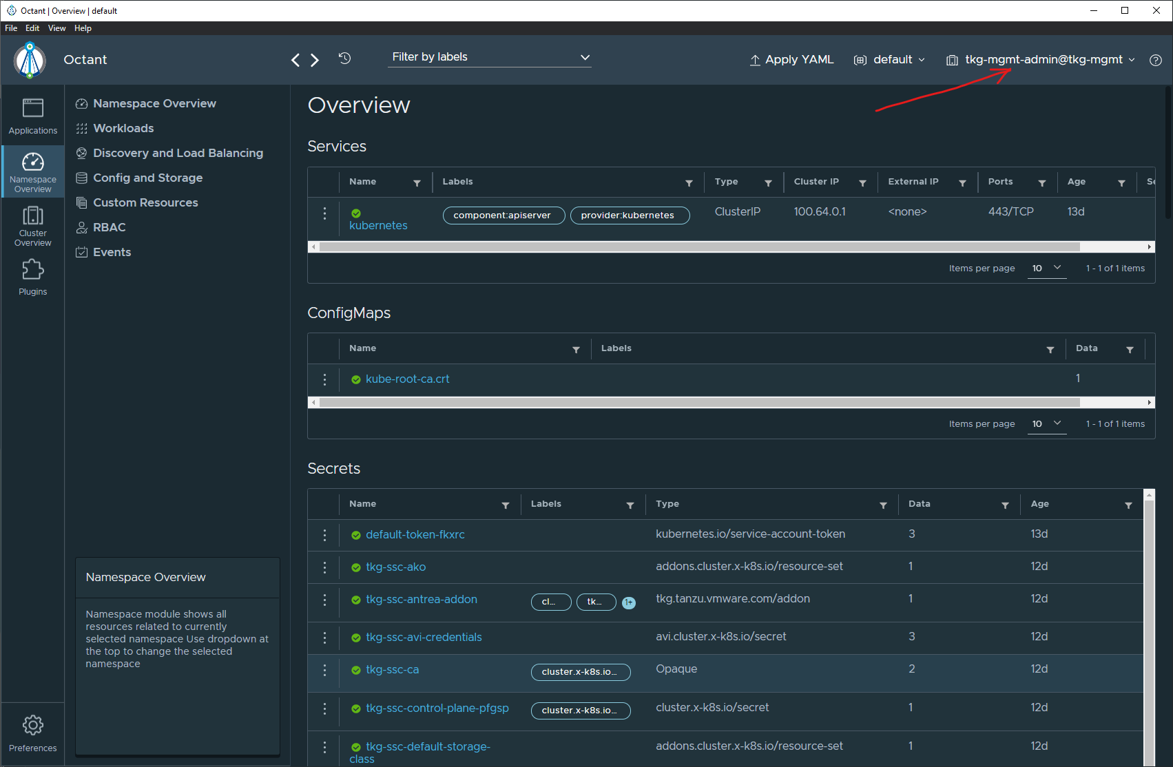
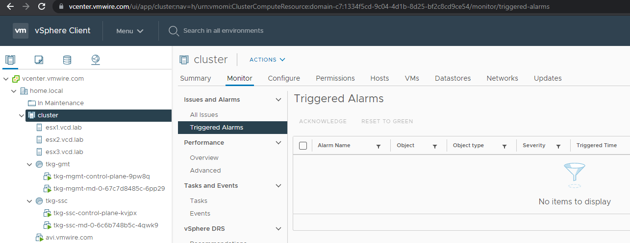
As soon as you launch Octant, it will default the view to the first context in the kube config file. For my setup, this is the tkg-mgmt context which is a TKGm management cluster.
Click on the context drop down menu at the top there will enable you to switch between contexts. The screenshot below shows the switch now to the tkg-ssc context, which in my environment is the shared services cluster.
Have a play around and once you start using Octant, you’ll likely stop using kubectl to query your Kubernetes clusters as Octant provides all that information in a neat tool.
As an example, here is a single view of the AKO config that I wrote about a few articles ago. This shows the avi-system namespace in the tkg-ssc cluster. You can see that there is the ako-0 pod that enables Kubernetes Ingress to the tkg-ssc cluster as well as other resources.
We can also look at other namespaces too. Lets take a look at the Kubernetes Dashboard namespace, remember that one? I wrote another article about it here.
Octant provides a nice view here, you can now see that the external ip for kubernetes dashboard is running on 172.16.4.34. Which is a lot simpler to obtain using Octant than running the command below
kubectl get -n kubernetes-dashboard svc kubernetes-dashboard-public
I probably used Kubernetes Dashboard as a bad example as you can see that Octant provides a much better user experience since Octant is able to show ALL Kubernetes clusters in a single interface when compared to Kubernetes Dashboard. This is because Kubernetes Dashboards runs inside a Kubernetes cluster, you would need to setup a dashboard on every single Kubernetes cluster and each dashboard would have its own endpoint. In simple terms, you’d have multiple browser tabs open to each Kubernetes Dashboard.
With Octant you’d have one. This is not the only benefit of Octant, I guess the best thing to do is install it and try it out.
This post details how you can enable Kubernetes clusters provisioned by the Container Service Extension to be accessible from outside of the cloud provider networks.
Providing great user experience to Kubernetes as a service from a cloud provider is important and as such enabling users to use their tools running on their personal devices to connect to remotely hosted Kubernetes clusters running in the cloud is a key feature of any cloud service.
A brief review of VCD networking
VMware Cloud Director provides network isolation between tenants by leveraging Geneve based networking provided by NSX-T. In simple terms, a tenant can utilize any network subnet without worrying about clashing with any other tenant using the same VCD cloud.
That means that a tenant with a private address space can deploy a Kubernetes cluster and utilize internal addresses for the Control Plane and the Worker nodes. A user can then access the Control Plane endpoint from inside of the tenant’s VDC and run kubectl commands happily and this will work – using a jumpbox for example. However, doing this from outside of the organization virtual datacenter will not work. Even if you tried to setup a DNAT rule to NAT to the internal IP of the Control Plane endpoint and mapping it to an external IP on the Edge gateway.
It doesn’t work because of the x.509 certificate that gets created when kubeadm creates the Kubernetes cluster. During this phase the certificate needs to include all subject alternative names (SANS) and with CSE, there is no way for the operator to define SANs during cluster provisioning with CSE.
If you attempt to connect using the external IP of the DNAT rule, you may get an error like the below:
kubectl get nodes -A --kubeconfig=tkg-vcd.yaml
Unable to connect to the server: x509: certificate is valid for 10.96.0.1, 192.168.0.100, not 10.149.1.101
For context, 192.168.0.100 is the internal IP of the Control Plane node. 10.149.1.101 is the external IP in the external IP pool allocated to this tenant’s Edge gateway. See the high-level architecture diagram.
How can we enable a better user experience to access a Kubernetes cluster running in a provider’s cloud?
Container Service Extension has a feature called ‘expose’ that can be used during Kubernetes cluster provisioning to enable the DNAT changes to the Edge gateway as well as including the external IP into the x.509 certificate SANs. This is done automatically and at the current CSE 3.0.4 version only through the vcd cse cli. Please see my previous post to learn more.
What is supported with CSE 3.0.4?
Expose works under the following conditions
cluster deployment via vcd cse cli only, no UI
new kubernetes cluster deployments only
you can deploy a cluster without expose initially but you cannot expose it later
you can deploy a cluster with expose and then un-expose it later, however you cannot re-expose it again
you are using NSX-T for VCD networking
the tenant has an Edge gateway defined for their VDCs
you have an external IP pool assigned to the Edge gateway
expose works with both TKGm and native k8s runtimes
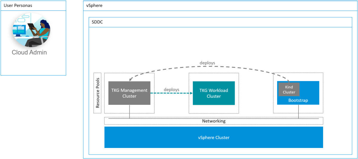
High Level Architecture
Deploying a Kubernetes cluster using expose
To enable this feature create a cluster config file anywhere on a terminal with the vcd cse cli installed. Below is an example of my config.yaml file, notice the lines for kind: use either TKGm for a TKGm runtime or native for a native runtime. Also change the template_name to suit the runtime.
The line under the spec section for expose: true will enable this feature.
Log into VCD using tenant credentials, by the way a tenant can use vcd cse cli to do this themselves to maintain self-service use cases. As a provider you don’t have to do this on a tenant’s behalf.
syntax is vcd login <cloud-url> <organization> <user>
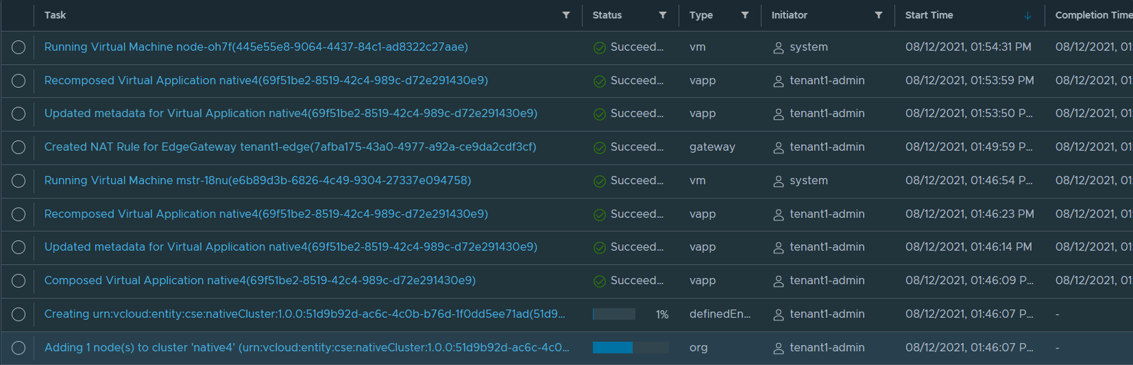
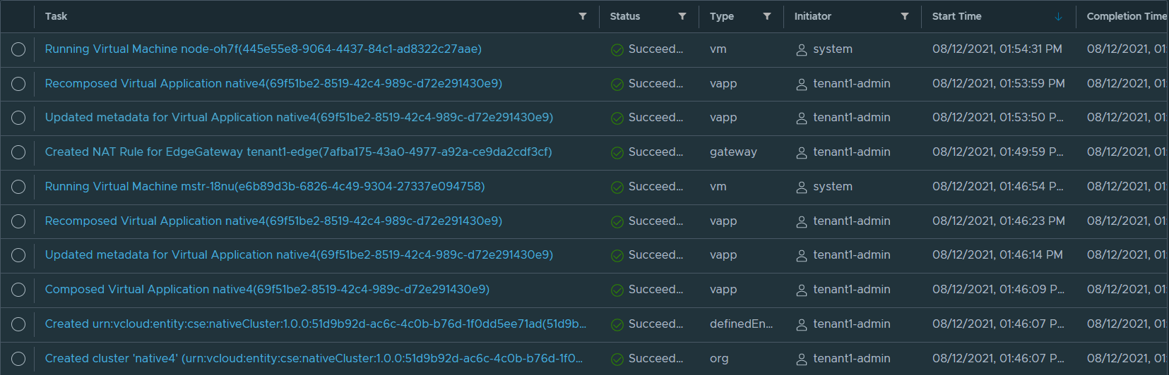
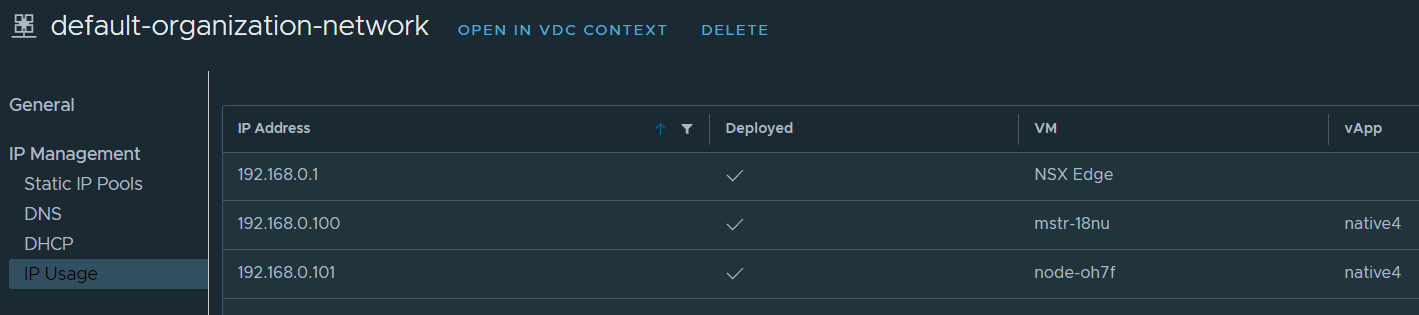
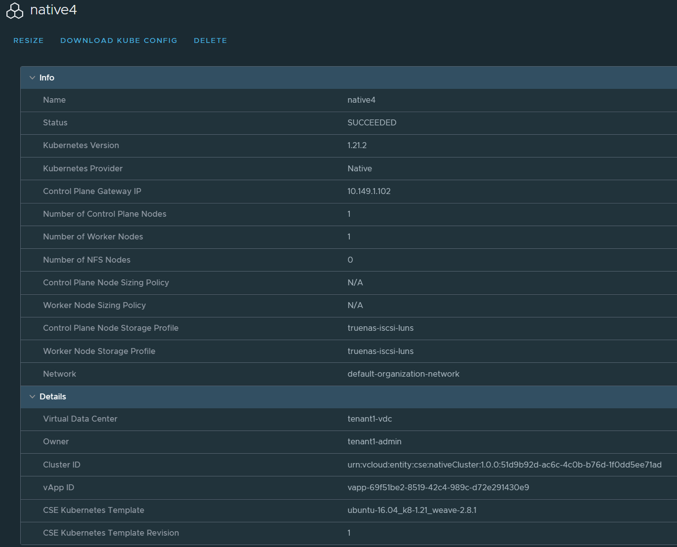
You’ll see in VCD that the tasks will kick off and your new cluster will be made available soon. What VCD does during deployment is it will pick up an IP address either using DHCP or static IP pool for the internal network (geneve NSX-T segment), in my example this is an IP on the 192.168.0.0/24 range and in the organization network named default-organization-network. This IP will be assigned to the master node of the Control Plane, in my case 192.168.0.100.
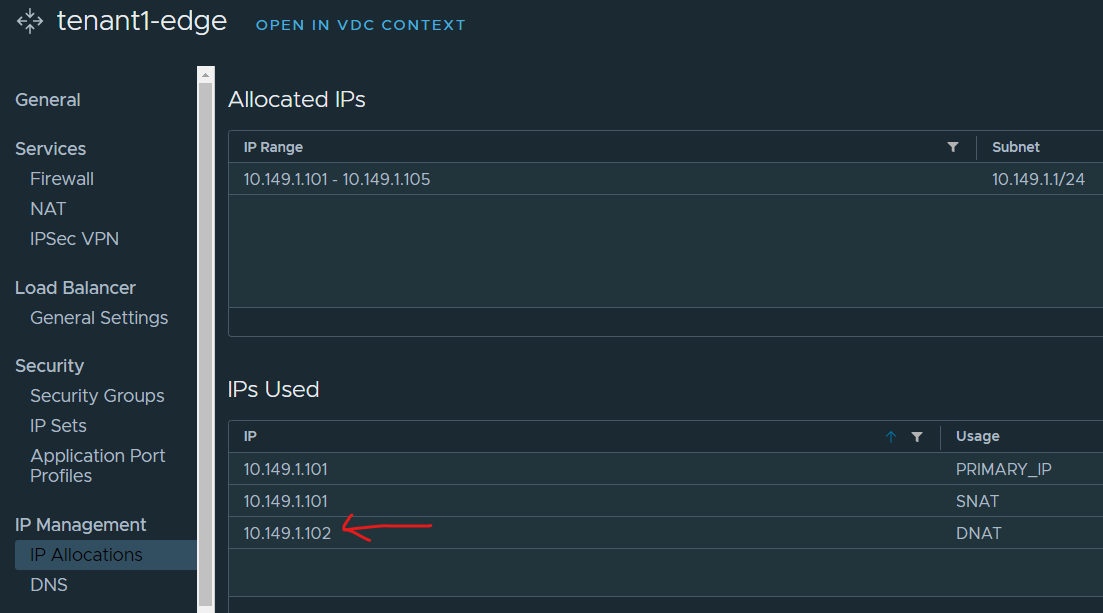
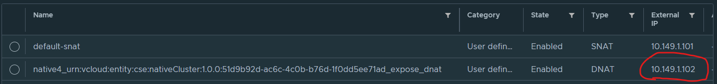
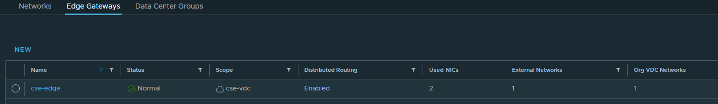
VCD will also create a DNAT rule and pick up the next available IP address from the external IP pool allocated to the Edge gateway. In my example this will be 10.149.1.102.
You can review the tasks for this workflow below
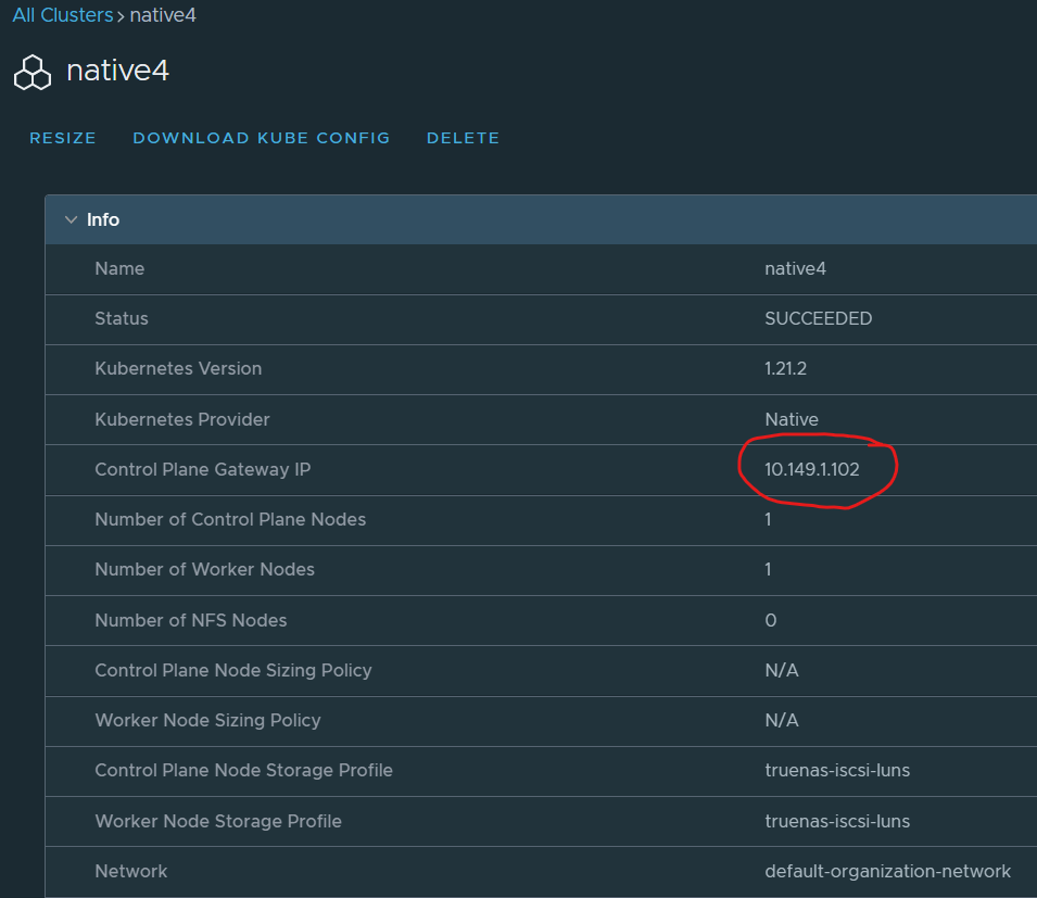
Once the cluster is ready, a user will just need to download the kubeconfig file onto his workstation and use the cluster.
Notice that the Control Plane Gateway IP is not an internal IP but in fact one of the external IPs of the organization VDC.
This is also reflected in the kubeconfig file on line 5. CSE expose uses the external IP and also adds all the IPs into the SANs.
Logging into the Kubernetes cluster from outside of the cloud
As long as your workstation can route to the Control Plane Gateway IP you will be able to access the cluster from anywhere. Note that you can allocate public IP addresses directly to the Edge gateway, and in fact I work with providers who do this using BGP to the NSX-T T0. CSE expose basically uses an IP from the external network IP allocation pool.
The easiest way to test connectivity is to use kubectl like the following example.
kubectl get nodes -A --kubeconfig=/root/kubeconfig-native4.yaml
Which will have a response of
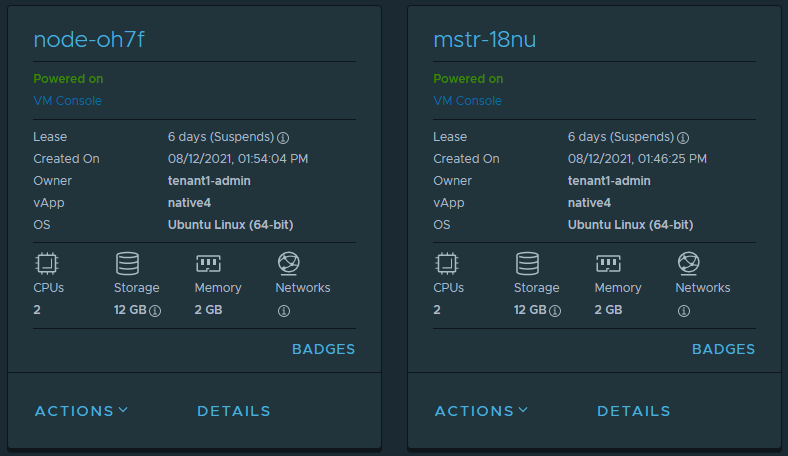
NAME STATUS ROLES AGE VERSION
mstr-18nu Ready control-plane,master 13m v1.21.2
node-oh7f Ready <none> 8m4s v1.21.2
This of course corresponds to what has been deployed in VCD.
This post covers how to install CSE 3.0.4 and enable it to work with VCD 10.2.2 and TKG 1.3. It is a simplified step by step guide on how to install CSE and get up and running with VCD as quickly as possible.
This post covers how to install CSE 3.0.4 and enable it to work with VCD 10.2.2 and TKG 1.3. It is a simplified step by step guide on how to install CSE and get up and running with VCD as quickly as possible.
A Short Introduction to Container Service Extension
Container Service Extension (CSE) is a VMware vCloud Director (VCD) extension that helps tenants create and work with Kubernetes clusters.
CSE brings Kubernetes as a Service to VCD, by creating customized VM templates (Kubernetes templates) and enabling tenant users to deploy fully functional Kubernetes clusters as self-contained vApps.
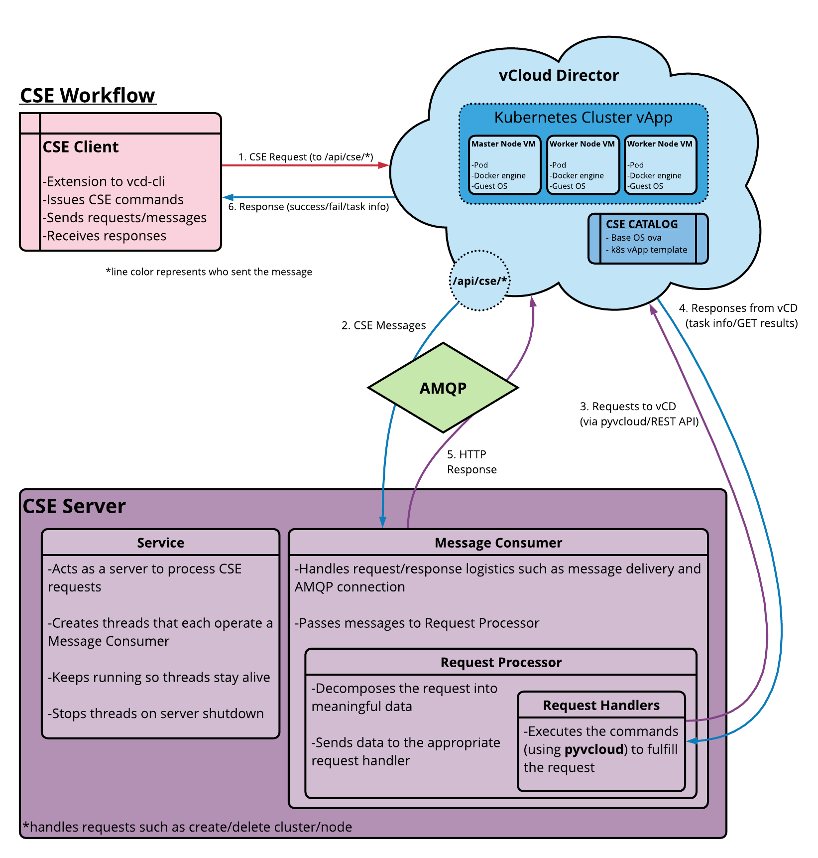
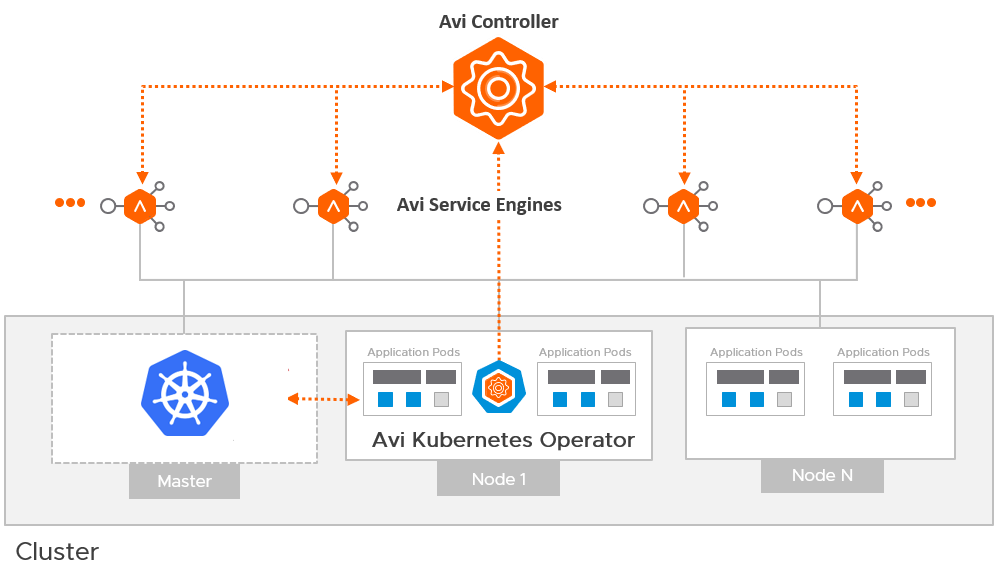
CSE has a server component that installs as a VCD extension. It exposes REST API endpoint points via VCD. CSE also has a client component that plugs in vcd-cli, communicates with the CSE server via the exposed API endpoints, and facilitates VCD users to create Kubernetes clusters in VCD. The following diagram illustrates the interactions between the components.
Please refer to the official documentation for more details.
However complicated the above diagram is, I aim to make the installation process super-simple. You can use this article to get up and running more quickly than using the official documentation above.
Preparing CSE Server
Choose a Linux distribution to use for the CSE server and deploy it into your vSphere management cluster and ensure that it can route to the public interface of your VMware Cloud Director instance.
We will be using MQTT which is embedded into VCD and therefore does not need RabbitMQ.
I used a Centos 8 VM with the following settings.
[Update] I’ve recently published a new post to show how you can deploy CSE server on Photon OS and run it as a Linux service. I recommend using Photon OS instead of CentOS.
Component
Specification
Centos 8 image
CentOS-8.4.2105-x86_64-boot.iso
vCPUs
1
Memory
2GB
Network
Management Network (same as vCenter, NSX-T Manager etc)
Routes
Routable to vCD public URL and has outbound Internet access.
Other configuration
DNS, NTP, VMware Tools
Perform the following on the Centos 8 VM
yum update
yum upgrade
yum install -y yum-utils
yum groupinstall -y development
yum -y install python38 python38-pip python38-devel
easy_install-3.8 pip
pip3 install --user vcd-cli
# Add /root/.local/bin to PATH to remove path errors for vcd-cli
PATH=$PATH:/root/.local/bin
export PATH
# Check vcd cli is installed correctly
vcd version
# Check python version
python3 --version
# Uninstall cryptography and humanfriendly
pip uninstall cryptography
pip uninstall humanfriendly
# Install CSE
pip3 install git+https://github.com/vmware/container-service-extension.git@3.0.4
# Check versions
cse version
vcd cse version
# To enable the CSE client in vcd-cli, make the ~/.vcd-cli directory
mkdir ~/.vcd-cli
# create a new file in ~/.vcd-cli/profiles.yaml
vi ~/.vcd-cli/profiles.yaml
# to include the following contents in that file
extensions:
- container_service_extension.client.cse
CSE Server Configuration
Generate a sample config.yaml file
cse sample -o config.yaml
Contents of my file
# Only one of the amqp or mqtt sections should be present. I am using MQTT, which is built into VCD 10.2 and is supported by CSE 3.
#amqp:
# exchange: cse-ext
# host: amqp.vmware.com
# password: guest
# port: 5672
# prefix: vcd
# routing_key: cse
# username: guest
# vhost: /
# using verify_ssl: false as this is a demo lab
mqtt:
verify_ssl: false
vcd:
api_version: '35.0'
host: vcd.vmwire.com
log: true
password: Vmware1!
port: 443
username: administrator
verify: false
vcs:
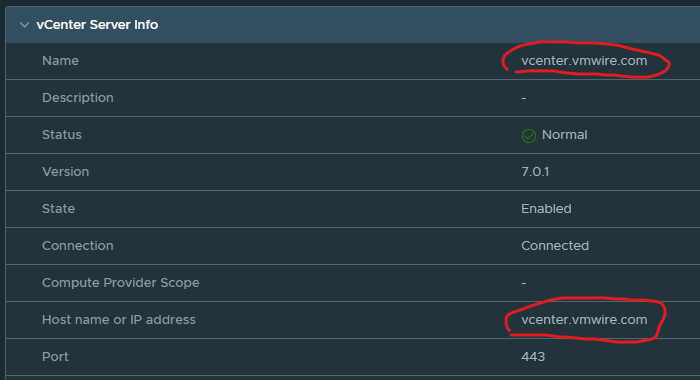
# vcenter name needs to be in FQDN format in vCD too, see screenshots below.
- name: vcenter.vmwire.com
password: Vmware1!
username: administrator@vsphere.local
verify: false
service:
enable_tkg_m: true
enforce_authorization: false
log_wire: false
processors: 15
telemetry:
enable: true
# ensure that you have setup a dedicated organization, VDC, internet accessible network and catalog for CSE.
broker:
  catalog: cse-catalog
  default_template_name: ubuntu-20.04_tkgm-1.20_antrea-0.11
  default_template_revision: 1
  ip_allocation_mode: pool
  network: default-organization-network
  org: cse
  remote_template_cookbook_url: https://raw.githubusercontent.com/vmware/container-service-extension-templates/tkgm/template.yaml
  storage_profile: 'truenas-iscsi-luns'
vdc: cse-vdc
A couple of notes on this config.yaml file.
Disable certificate verification if you do not have signed SSL certificates or this is for lab purposes and you are comfortable with this.
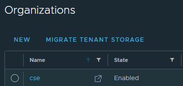
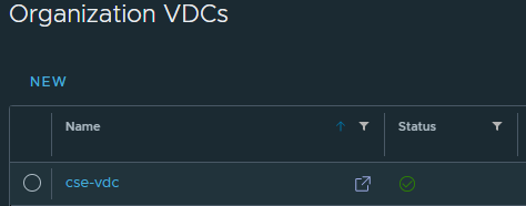
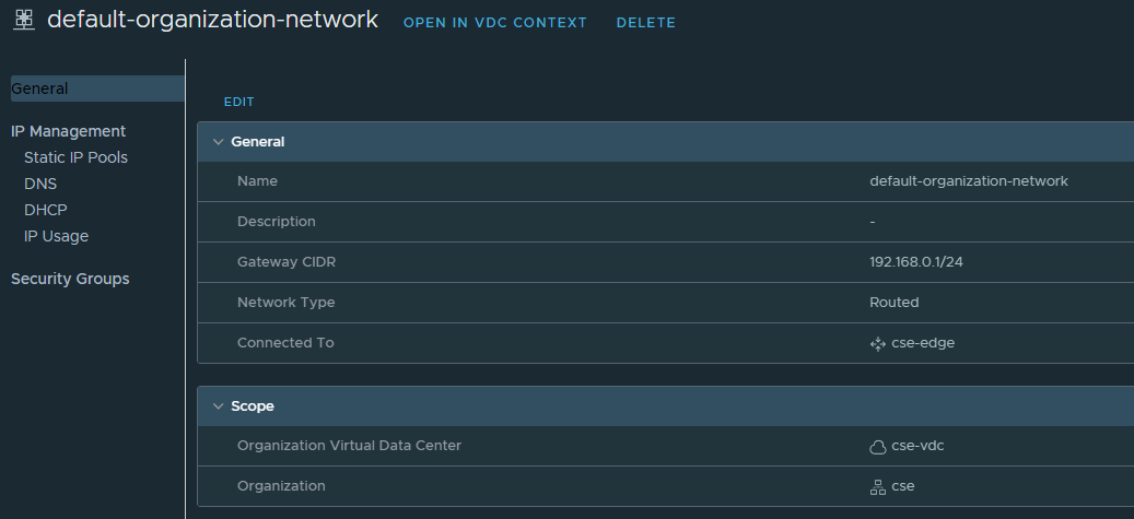
Create a new organization, org VDC (any allocation model), catalog, organization network (with access to the internet). See my screenshots below.
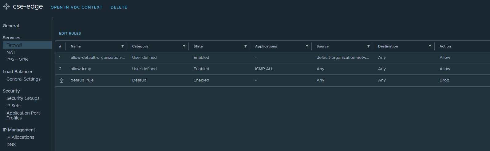
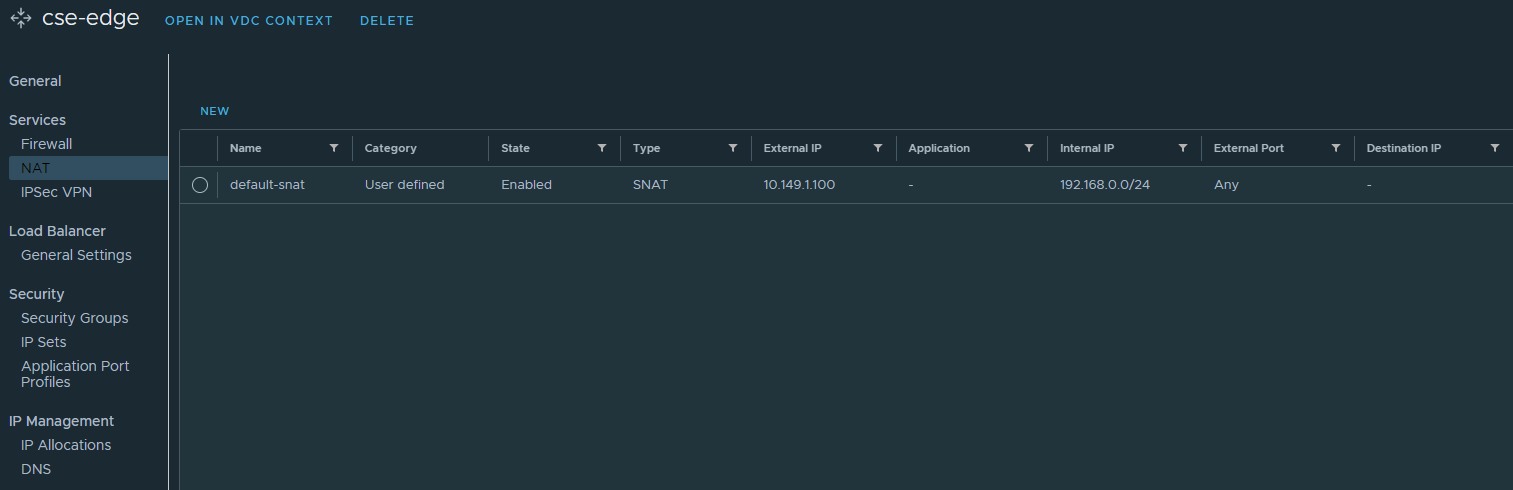
If you prefer to use an org routed network behind a NSX-T T0 then don’t forget to setup the Edge firewall and source NAT rules, I’ve provided screenshots below. Otherwise you can use a direct connect organization network backed by a port group instead. Just ensure that this network has outbound internet access.
Create a static IP pool for this organization network so that the VMs that CSE prepares can be configured with networking details.
Ensure that this new org corresponds to the settings under the broker section in the config.yaml file.
the default_template_name can correspond to any of the templates listed in this file, look for the name parameter. This file is the TKGm specific file, if you also want to support native upstream k8s then you can use this file instead. In fact you can support both at the same time. To support both, first install CSE with one config file (TKGm) and then upgrade CSE with the other config file (native). Or use my script here that does everything for you.
Read this documentation for pointers or place a comment below and I’ll help you out.
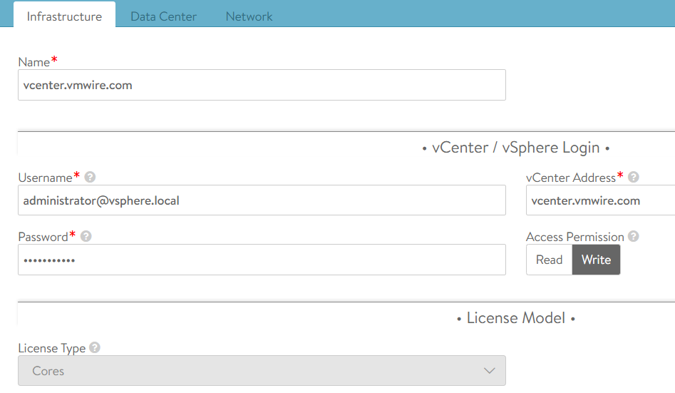
Under the vcs section, you’ll notice that you need to specify a vCenter name, this has to be the same name but in a FQDN format as the vCenter Server Instance setting under Infrastructure Resources in VCD. Like my settings below:
Once everything is ready you will need to encrypt the config file as CSE will only work with an encrypted file.
CSE will ask you for an encryption password, please keep a note of it.
Install CSE
Remove group and unnecessary permissions from the config file, CSE will complain if you don’t.
chmod 600 encrypted-config.yaml
First check the validity of the config file before installing CSE.
cse check encrypted-config.yaml
Install CSE with this command
cse install -c encrypted-config.yaml
This activity will take a long time, over an hour as CSE will do the following:
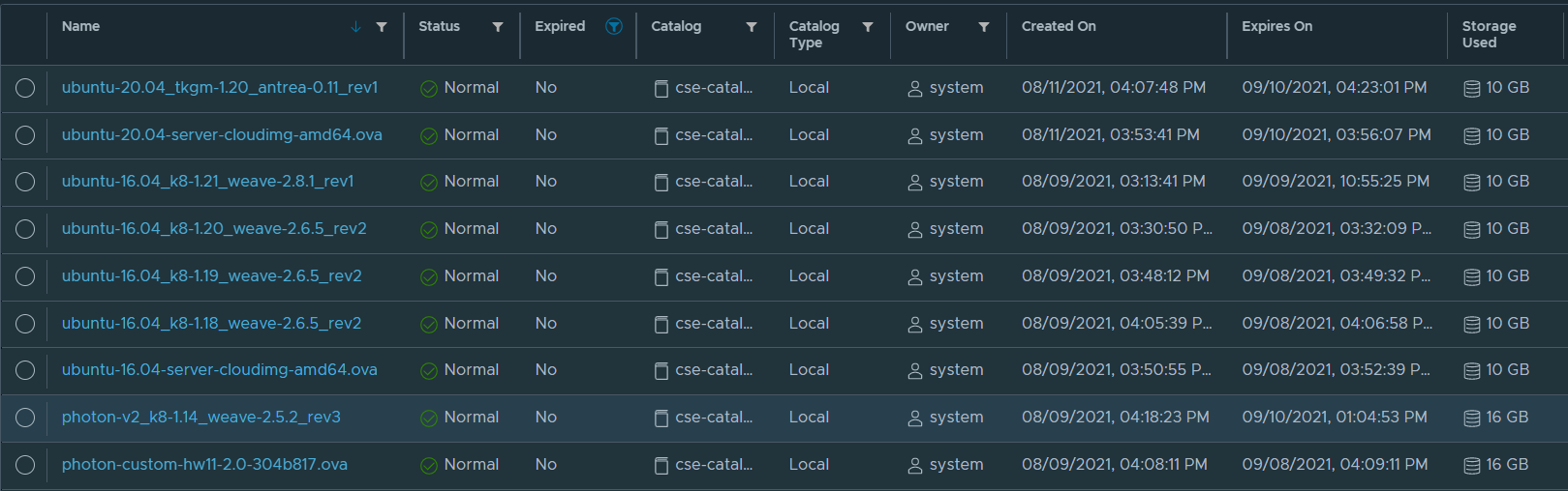
Download all of the OVAs from the template specification file. There are five templates to download
For each OVA, it will upload to the VCD cse organization catalog, in my case cse-catalog under the cse organization
Create a vApp for each catalog
Prepare the VM by download bits
Upload the VM to the catalog as a template
Once complete you’ll be able to see the following templates in the catalog. Note that I’ve enabled CSE to use both TKGm and native upstream k8s, hence the many templates listed here.
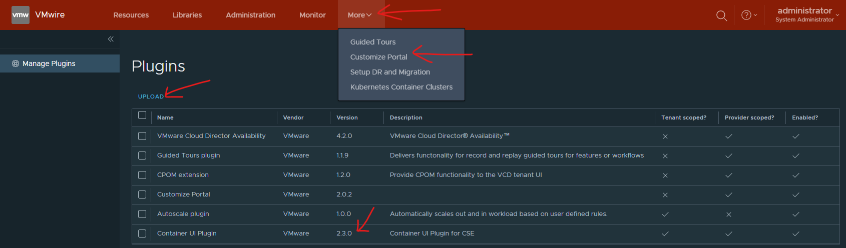
Enable CSE 2.3 Plugin in VCD
CSE 3.0.4 does not support the default CSE 2.2 plugin that is enabled by default with VCD 10.2.2. We need to disable and remove the CSE 2.2 plugin and upload and enable the CSE 2.3 plugin instead.
This plugin is available from this link on my.vmware.com.
To install it go to the /Provider portal and under More, use the Customize Portal.
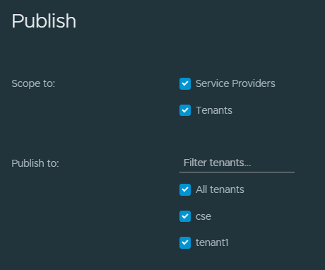
And then publish the plugin to all/select Tenants.
Enable Tenant access to CSE
Note that CSE supports both TKGm and native k8s runtimes at the same time, and you can provision both with VCD.
TKG related options won’t show up in vcd-cli, unless explicitly enabled. To enable TKG options in vcd-cli, set the following environment variable
export CSE_TKG_M_ENABLED=True
First login to VCD using the vcd cli
vcd login vcd.vmwire.com system administrator --password Vmware1! -w -i
Enable Global Roles to use CSE or Configure Rights Bundles
The quickest way to get CSE working is to add the relevant rights to the Organization Administrator role. You can create a custom rights bundle and create a custom role for the k8s admin tenant persona if you like. I won’t cover that in this post.
Log in as the /Provider and go to the Administration menu and click on Global Roles on the left.
Edit the Organization Administrator role and scroll all the way down to the bottom and click both the View 8/8 and Manage 12/12, then Save.
Starting CSE
First lets check our installation
cse check encrypted-config.yaml --check-install
Run CSE from command line
# Run server in foreground
cse run --config config.yaml

# Run server in background
nohup cse run --config config.yaml > nohup.out 2>&1 &
You can also run CSE as a service, please refer to this link if you prefer to do this instead.
Deploying a TKG cluster as a Tenant
Congratulations, now we’re ready to deploy a k8s cluster.
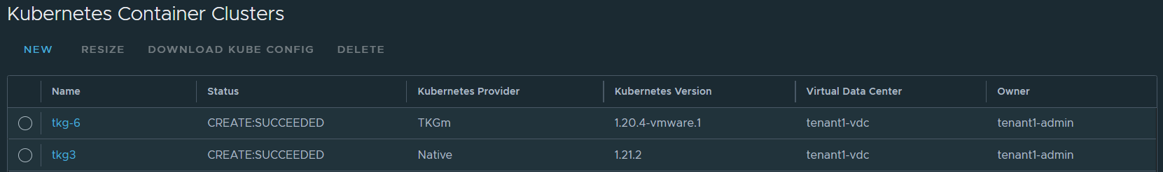
Log into VCD as a tenant and go to More, Kubernetes Container Clusters.
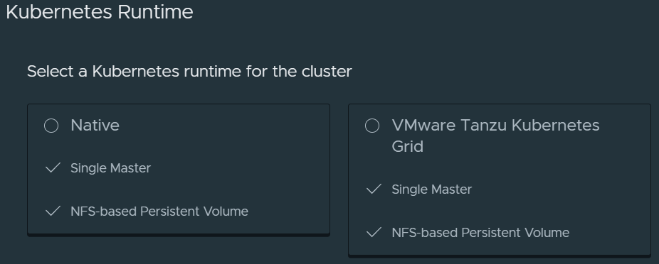
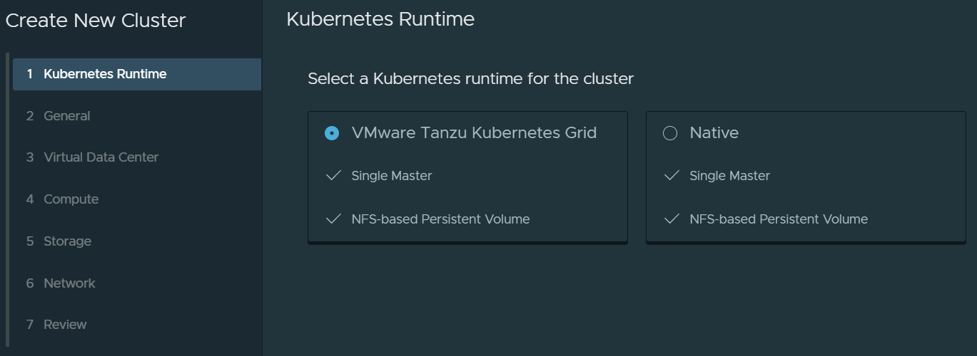
Click on New and you should now see an option to deploy a Native Kubernetes runtime or a VMware Tanzu Kubernetes Grid runtime. VCD also supports vSphere with Tanzu as well (which is not installed as part of this article). You’ll see a third tile here if you did enable vSphere with Tanzu (TKGs).
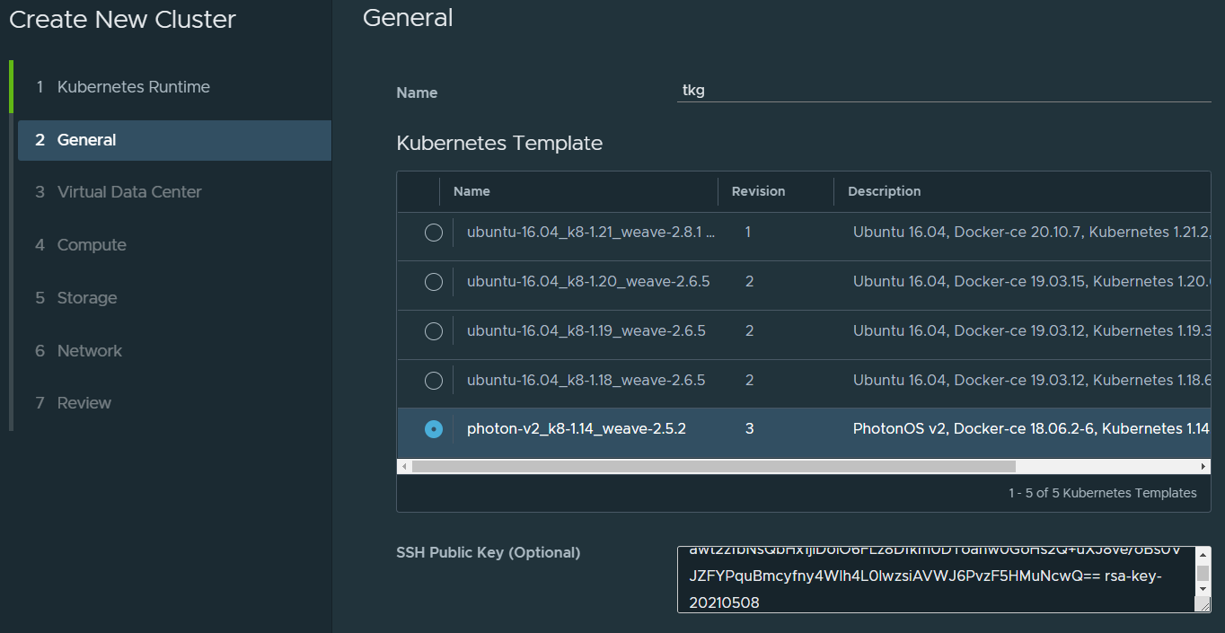
On the next page, give the k8s cluster a name, select a runtime and optionally paste in your SSH public key for easier access to the Kubernetes cluster later.
Proceed as following screenshots.
CSE 3.0.4 does not support multi-master, i.e., more than one node for the Control Plane. This is coming in a future release.
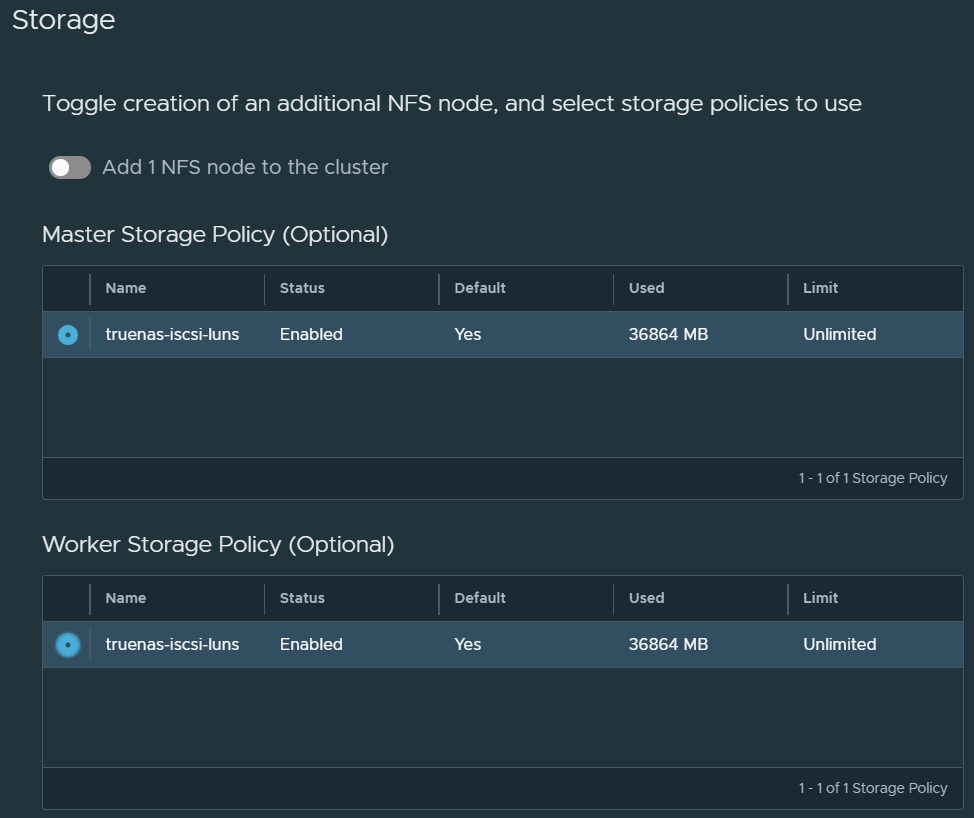
Next select the storage policies that the Control Plane node and the Worker node(s) will be deployed into. You can also opt to deploy another node to use as persistent volumes through NFS.
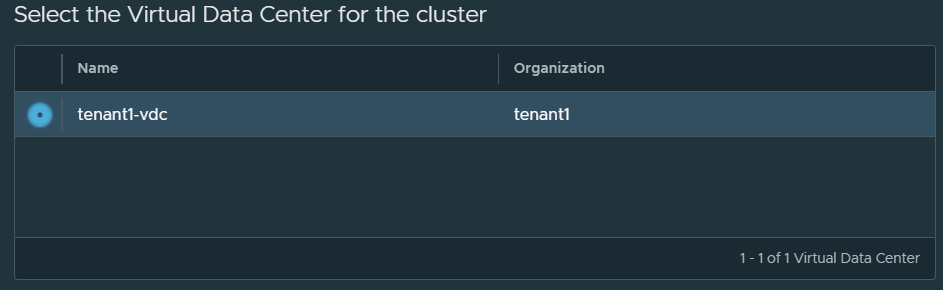
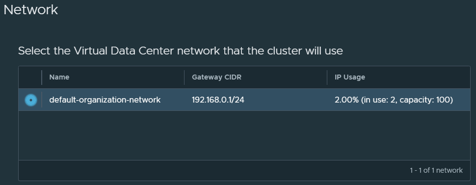
Select the network.
Review the final page and click on Finish. CSE will now deploy the TKG cluster for you and it will be ready once all nodes are up and running. You’ll see the following once ready.
Which you can also see with this command in CSE
vcd cse cluster list
[root@cse .vcd-cli]# vcd cse cluster list
Name    Org      Owner          VDC          K8s Runtime    K8s Version       Status
------  -------  -------------  -----------  -------------  ----------------  ----------------
tkg     tenant1  tenant1-admin  tenant1-vdc  native         upstream 1.14.10  CREATE:SUCCEEDED
Only thing left to do is download the Kube Config file and login with kubectl.
Useful commands
# Login to VCD
vcd login vcd.vmwire.com system administrator --password Vmware1! -w -i
# Register CSE extension with VCD
vcd system extension create cse cse cse vcdext '/api/cse, /api/cse/.*, /api/cse/.*/.*'
# List VCD extentions
vcd system extension list
# Describe CSE extension
vcd system extension info cse
# Describe CSE configuration
vcd cse system info
# List organization VDCs with CSE enabled
vcd cse ovdc list
# Enable CSE for org VDC
vcd cse ovdc enable --native --org tenant1 tenant1-vdc
# Look at CSE logs
cat /root/.cse-logs/cse-server-info.log, /root/.cse-logs/cse-server-debug.log
# Tail the CSE logs
tail -f /root/.cse-logs/cse-server-info.log, /root/.cse-logs/cse-server-debug.log
# Upgrading CSE or changing config file parameters, e.g., changing verify_ssl certs to true, note the skip-template-creation which will save you a lot of time
cse upgrade --config <config_file> --skip-template-creation
# Get infor for a cluster named tkg
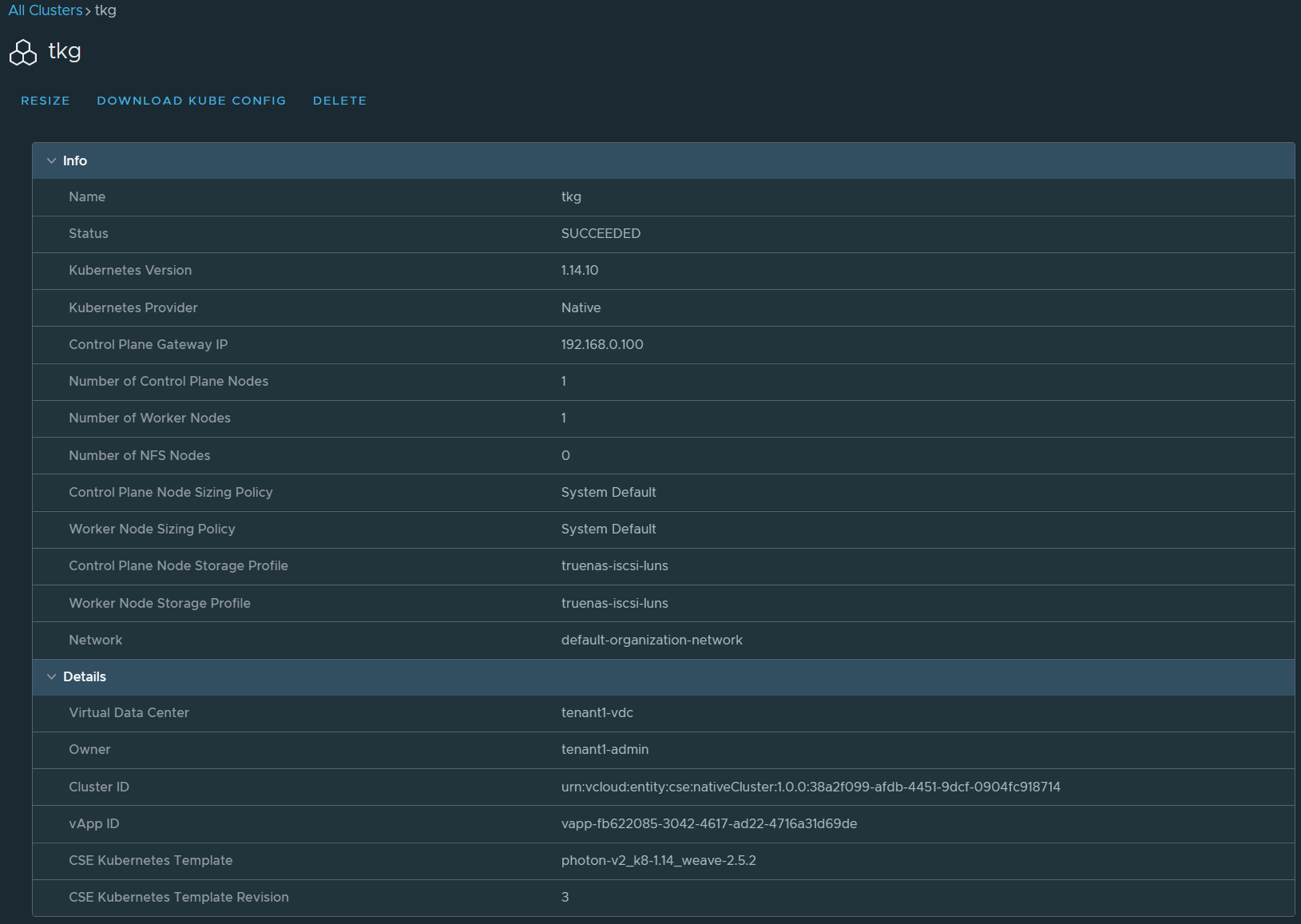
vcd cse cluster info tkg
# Login as a tenant user
vcd login vcd.vmwire.com tenant1 tenant1-admin -i -w
# Deploy tkg cluster using the command line
vcd cse cluster apply tkg7.yaml
In this post I show how to deploy the Kubernetes Dashboard onto a Tanzu Kubernetes Grid cluster.
Dashboard provides information on the state of Kubernetes resources in your cluster and on any errors that may have occurred.
Dashboard is a web-based Kubernetes user interface. You can use Dashboard to deploy containerized applications to a Kubernetes cluster, troubleshoot your containerized application, and manage the cluster resources. You can use Dashboard to get an overview of applications running on your cluster, as well as for creating or modifying individual Kubernetes resources (such as Deployments, Jobs, DaemonSets, etc). For example, you can scale a Deployment, initiate a rolling update, restart a pod or deploy new applications using a deploy wizard.
Dashboard also provides information on the state of Kubernetes resources in your cluster and on any errors that may have occurred.
In the previous post I prepared NSX ALB for Tanzu Kubernetes Grid ingress services. In this post I will deploy a new TKG cluster and use if for Tanzu Shared Services.
Tanzu Kubernetes Grid includes binaries for tools that provide in-cluster and shared services to the clusters running in your Tanzu Kubernetes Grid instance. All of the provided binaries and container images are built and signed by VMware.
A shared services cluster, is just a Tanzu Kubernetes Grid workload cluster used for shared services, it can be provisioned using the standard cli command tanzu cluster create, or through Tanzu Mission Control.
You can add functionalities to Tanzu Kubernetes clusters by installing extensions to different cluster locations as follows:
The Harbor service runs on a shared services cluster, to serve all the other clusters in an installation. The Harbor service requires the Contour service to also run on the shared services cluster. In many environments, the Harbor service also benefits from External DNS running on its cluster, as described in Harbor Registry and External DNS.
Some extensions require or are enhanced by other extensions deployed to the same cluster:
Contour is required by Harbor, External DNS, and Grafana
Prometheus is required by Grafana
External DNS is recommended for Harbor on infrastructures with load balancing (AWS, Azure, and vSphere with NSX Advanced Load Balancer), especially in production or other environments in which Harbor availability is important.
Each Tanzu Kubernetes Grid instance can only have one shared services cluster.
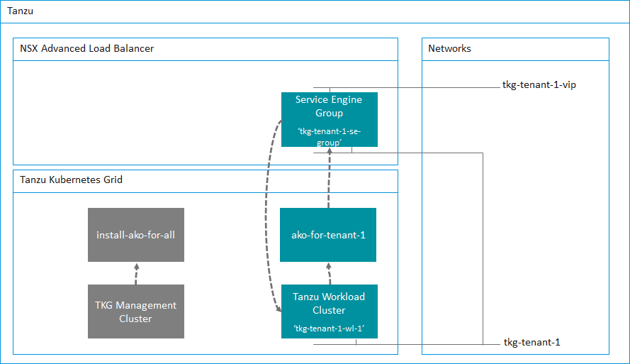
Relationships
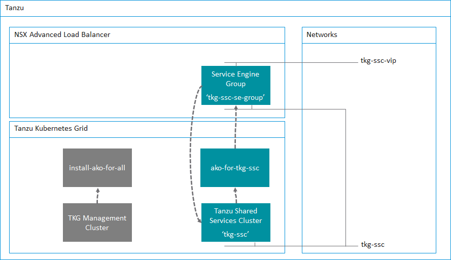
The following table shows the relationships between the NSX ALB system, the TKG cluster deployment config and the AKO config. It is important to get these three correct.
Avi Controller
TKG cluster deployment file
AKO Config file
Service Engine Group name tkg-ssc-se-group
AVI_LABELS
'cluster': 'tkg-ssc'
clusterSelector:
  matchLabels:
   cluster: tkg-ssc

serviceEngineGroup: tkg-ssc-se-group
TKG Cluster Deployment Config File – tkg-ssc.yaml
Lets first take a look at the deployment configuration file for the Shared Services Cluster.
I’ve highlighted in bold the two key value pairs that are important in this file. You’ll notice that
AVI_LABELS: |
    'cluster': 'tkg-ssc'
We are labeling this TKG cluster so that Avi knows about it. In addition the other key value pair
AVI_SERVICE_ENGINE_GROUP: tkg-ssc-se-group
This ensures that this TKG cluster will use the service engine group named tkg-ssc-se-group.
While we have this file open you’ll notice that the long certificate under AVI_CA_DATA_B64 is the copy and paste of the Avi Controller certificate that I copied from the previous post.
Take some time to review my cluster deployment config file for the Shared Services Cluster below. You’ll see that you will need to specify the VIP network for NSX ALB to use
AVI_DATA_NETWORK: tkg-ssc-vip
AVI_DATA_NETWORK_CIDR: 172.16.4.32/27
Basically, any key that begins with AVI_ needs to have the corresponding setting configured in NSX ALB. This is what we prepared in the previous post.
The next file we need to configure is the AKODeploymentConfig file, this file is used by Kubernetes to ensure that the L4 load balancing is using NSX ALB.
I’ve highlighted some settings that are important.
clusterSelector:
  matchLabels:
    cluster: tkg-ssc
Here we are specifying a cluster selector for AKO that will use the name of the cluster, this corresponds to the following setting in the tkg-ssc.yaml file.
AVI_LABELS: |
  'cluster': 'tkg-ssc'
The next key value pair specifies what Service Engines to use for this TKG cluster. This is of course what we configured within Avi in the previous post.
Setup the new AKO configuration before deploying the new TKG cluster
Before deploying the new TKG cluster, we have to setup a new AKO configuration. To do this run the following command under the TKG Management Cluster context.
kubectl apply -f <Path_to_YAML_File>
Which in my example is
kubectl apply -f tkg-ssc-akodeploymentconfig.yaml
You can use the following to check that that was successful.
kubectl get akodeploymentconfig
root@photon-manager [ ~/.tanzu/tkg/clusterconfigs ]# kubectl get akodeploymentconfig
NAME AGE
ako-for-tkg-ssc 3d19h
You can also show additional details by using the kubectl describe command
For any new AKO configs that you need, just take a copy of the .yaml file and edit the contents that correspond to the new AKO config. For example, to create another AKO config for a new tenant, take a copy of the tkg-ssc-akodeploymentconfig.yaml file and give it a new name such as tkg-tenant-1-akodeploymentconfig.yaml, and change the following highlighted key value pairs.
root@photon-manager [ ~/.tanzu/tkg/clusterconfigs ]# tanzu cluster list --include-management-cluster NAME NAMESPACE STATUS CONTROLPLANE WORKERS KUBERNETES ROLES PLAN tkg-ssc default running 1/1 1/1 v1.20.5+vmware.2 tanzu-services dev tkg-mgmt tkg-system running 1/1 1/1 v1.20.5+vmware.2 management dev
Add the key value pair of cluster=tkg-ssc to label this cluster and complete the setup of AKO.
kubectl label cluster tkg-ssc cluster=tkg-ssc
Once the cluster is labelled, switch to the tkg-ssc context and you will notice a new namespace named “avi-system” being created and a new pod named “ako-0” being started.
root@photon-manager [ ~/.tanzu/tkg/clusterconfigs ]# kubectl get ns
NAME STATUS AGE
avi-system Active 3d18h
cert-manager Active 3d15h
default Active 3d19h
kube-node-lease Active 3d19h
kube-public Active 3d19h
kube-system Active 3d19h
kubernetes-dashboard Active 3d16h
tanzu-system-monitoring Active 3d15h
tkg-system Active 3d19h
tkg-system-public Active 3d19h
root@photon-manager [ ~/.tanzu/tkg/clusterconfigs ]# kubectl get pods -n avi-system
NAME READY STATUS RESTARTS AGE
ako-0 1/1 Running 0 3d18h
Summary
We now have a new TKG Shared Services Cluster up and running and configured for Kubernetes ingress services with NSX ALB.
In the next post I’ll deploy the Kubernetes Dashboard onto the Shared Services Cluster and show how this then configures the NSX ALB for ingress services.
In this post I describe how to setup NSX ALB (Avi) in preparation for use with Tanzu Kubernetes Grid, more specifically, the Avi Kubernetes Operator (AKO).
AKO is a Kubernetes operator which works as an ingress controller and performs Avi-specific functions in a Kubernetes environment with the Avi Controller. It runs as a pod in the cluster and translates the required Kubernetes objects to Avi objects and automates the implementation of ingresses/routes/services on the Service Engines (SE) via the Avi Controller.
Avi Kubernetes Operator Architecture
First lets describe the architecture for TKG + AKO.
For each tenant that you have, you will have at least one AKO configuration.
A tenant can have one or more TKG workload clusters and more than one TKG workload cluster can share an AKO configuration. This is important to remember for multi-tenant services when using Tanzu Kubernetes Grid. However, you can of course configure an AKO config for each TKG workload cluster if you wish to provide multiple AKO configurations. This will require more Service Engines and Service Engine Groups as we will discuss further below.
So as a minimum, you will have several AKO configs. Let me summarize in the following table.
AKO Config
Description
Specification
install-ako-for-all
The default ako configuration used for the TKG Management Cluster and deployed by default
Provider side ako configuration for the TKG Management Cluster only.
ako-for-tkg-ssc
The ako configuration for the Tanzu Shared Services Cluster
Provider side AKO configuration for the Tanzu Shared Services Cluster only.
tkg-ssc-akodeploymentconfig.yaml
ako-for-tenant-1
The ako configuration for Tenant 1
AKO configuration prepared by the Provider and deployed for the tenant to use.
tkg-tenant-1-akodeploymentconfig.yaml
ako-for-tenant-x
The ako configuration for Tenant x
Although TKG deploys a default AKO config, we do not use any ingress services for the TKG Management Cluster. Therefore we do not need to deploy a Service Engine Group and Service Engines for this cluster.
Service Engine Groups and Service Engines are only required if you need ingress services to your applications. We of course need this for the Tanzu Shared Services and any applications deployed into a workload cluster.
I will go into more detail in a follow-up post where I will demonstrate how to setup the Tanzu Shared Services Cluster that uses the preparation steps described in this post.
Lets start the Avi Controller configuration. Although I am using the Tanzu Shared Services Cluster as an example for this guide, the same steps can be repeated for all additional Tanzu Kubernetes Grid workload clusters. All that is needed is a few changes to the .yaml files and you’re good to go.
Clouds
I prefer not to use the Default-Cloud, and will always create a new cloud.
The benefit to using NSX ALB in write mode (Orchestration mode) is that NSX ALB will orchestrate the creation of service engines for you and also scale out more service engines if your applications demand more capacity. However, if you are using VMware Cloud on AWS, this is not possible due to restrictions with the RBAC constraints within VMC so only non-orchestration mode is possible with VMC.
In this post I’m using my home lab which is running vSphere.
Navigate to Infrastructure, Clouds and click on the CREATE button and select the VMware vCenter/VMware vSphere ESX option. This post uses vCenter as a cloud type.
Fill in the details as my screenshots show. You can leave the IPAM Profile settings empty for now, we will complete these in the next step.
Select the Data Center within your vSphere hierarchy. I’m using my home lab for this example. Again leave all the other settings on the defaults.
The next tab will take you to the network options for the management network to use for the service engines. This network needs to be routable between the Avi Controller(s) and the service engines.
The network tab will show you the networks that it finds from the vCenter connection, I am using my management network. This network is where I run all of the management appliances, such as vCenter, NSX-T, Avi Controllers etc.
Its best to configure a static IP pool for the service engines. Generally, you’ll need just a handful of IP addresses as each service engine group will have two service engines and each service engine will only need one management IP. A service engine group can provide Kubernetes load balancing services for the entire Kubernetes cluster. This of course depends on your sizing requirements, and can be reviewed here. For my home lab, fourteen IP addresses is more than sufficient for my needs.
Service Engine Group
While we’re in the Infrastructure settings lets proceed to setup a new Service Engine Group. Navigate to Infrastructure, Service Engine Group, select the new cloud that we previously setup and then click on the CREATE button. Its important that you ensure you select your new cloud from that drop down menu.
Give your new service engine group a name, I tend to use a naming format such as tkg-<cluster-name>-se-group. For this example, I am setting up a new SE group for the Tanzu Shared Services Cluster.
Reduce the maximum number of service engines down if you wish. You can leave all other settings on defaults.
Click on the Advanced tab to setup some vSphere specifics. Here you can setup some options that will help you identify the SEs in the vSphere hierarchy as well as placing the SEs into a VM folder and options to include or exclude compute clusters or hosts and even an option to include or exclude a datastore.
Service Engine groups are important as they are the boundary with which TKG clusters will use for L4 services. Each SE Group needs to have a unique name, this is important as each TKG workload cluster will use this name for its AKODeploymentConfig file, this is the config file that maps a TKG cluster to NSX ALB for L4 load balancing services.
With TKG, when you create a TKG workload cluster you must specify some key value pairs that correspond to service engine group names and this is then applied in the AKODeploymentConfig file.
The following table shows where these relationships lie and I will go into more detail in a follow-up post where I will demonstrate how to setup the Tanzu Shared Services Cluster.
Avi Controller
TKG cluster deployment file
AKO Config file
Service Engine Group name tkg-ssc-se-group
AVI_LABELS
'cluster': 'tkg-ssc'
clusterSelector:
  matchLabels:
   cluster: tkg-ssc

serviceEngineGroup: tkg-ssc-se-group
Networks
Navigate to Infrastructure, Networks, again ensure that you select your new cloud from the drop down menu.
The Avi Controller will show you all the networks that it has detected using the vCenter connection that you configured. What we need to do in this section is to configure the networks that NSX ALB will use when configuring a service for Kubernetes to use. Generally, depending on how you setup your network architecture for TKG, you will have one network that the TKG cluster will use and another for the front-end VIP. This network is what you will use to expose the pods on. Think of it as a load balancer DMZ network.
In my home lab, I use the following setup.
Network
Description
Specification
tkg-mgmt
TKG Management Cluster
Network: 172.16.3.0/27 Static IP Pools: 172.16.3.26 – 172.16.3.29
tkg-ssc
TKG Shared Services Cluster
Network: 172.16.3.32/27 Static IP Pools: 172.16.3.59 – 172.16.3.62
tkg-ssc-vip
TKG Shared Services Cluster front-end VIPs
Network: 172.16.4.32/27 Static IP Pools: 172.16.4.34 – 172.16.4.62
IPAM Profile
Create an IPAM profile by navigating to Templates, Profiles, IPAM/DNS Profiles and clicking on the CREATE button and select IPAM Profile.
Select the cloud that you setup above and select all of the usable networks that you will use for applications that will use the load balancer service from NSX ALB. You want to select the networks that you configured in the step above.
Avi Controller Certificate
We also need the SSL certificate used by the Avi Controller, I am using a signed certificate in my home lab from Let’s Encrypt, which I wrote about in a previous post.
Navigate to Templates, Security, SSL/TLS Certificates, click on the icon with a downward arrow in a circle next to the certificate for your Avi Controller, its normally the first one in the list.
Click on the Copy to clipboard button and paste the certificate into Notepad++ or similar.
At this point we have NSX ALB setup for deploying a new TKG workload cluster using the new Service Engine Group that we have prepared. In the next post, I’ll demonstrate how to setup the Tanzu Shared Services Cluster to use NSX ALB for ingress services.
This topic explains how to install and initialize the Tanzu command line interface (CLI) on a bootstrap machine. I’ve found that using Photon OS 4.0 is the fastest and most straightforward method to get going with Tanzu.
A quick post on how to setup a Tanzu Kubernetes Grid bootstrap VM using Photon OS.
This topic explains how to install and initialize the Tanzu command line interface (CLI) on a bootstrap machine. I’ve found that using Photon OS 4.0 is the fastest and most straightforward method to get going with Tanzu. I’ve tried Ubuntu and CentOS but these require a lot more preparation with pre-requisites and dependencies such as building a VM from an ISO, and installing Docker which Photon OS already comes with. The other thing I’ve noticed with Linux distros such as Ubuntu is that other things might interfere with your Tanzu deployment. Apparmor and the ufw firewall come to mind.
The Tanzu bootstrap machine is the laptop, host, or server that you deploy management and workload clusters from, and that keeps the Tanzu and Kubernetes configuration files for your deployments. The bootstrap machine is typically local, but it can also be a physical machine or VM that you access remotely. We will be using a ready built Photon OS OVA that is supported by VMware.
Photon OS, is an open-source minimalist Linux operating system from VMware that is optimized for cloud computing platforms, VMware vSphere deployments, and applications native to the cloud.
Photon OS is a Linux container host optimized for vSphere and cloud-computing platforms such as Amazon Elastic Compute and Google Compute Engine. As a lightweight and extensible operating system, Photon OS works with the most common container formats, including Docker, Rocket, and Garden. Photon OS includes a yum-compatible, package-based lifecycle management system called tdnf.
Once the Tanzu CLI is installed, the second and last step to deploying Tanzu Kubernetes Grid is using the Tanzu CLI to create or designate a management cluster on each cloud provider that you use. The Tanzu CLI then communicates with the management cluster to create and manage workload clusters on the cloud provider.
Deploy that ova using vCenter Linux Guest Customization and ensure that you deploy it on the same network as the TKG management cluster network that you intend to use. This is important as the bootstrap will set up a temporary kind cluster on Docker that will then be moved over to the TKG management cluster.
Ensure your VM has a minimum of 6GB of RAM. You can read up on other pre-requisites here.
Login using root, with password of changeme, you will be asked to update the root password. All the steps below are done using the root account, if you wish to use a non root account with Photon OS, ensure that you add that account to the docker group, more details in this link here.
Install the tar package, which we will need later to extract the Tanzu CLI.
tdnf install tar
First thing to do is create a new directory called /tanzu.
mkdir /tanzu
and then go into that directory, we will be performing most tasks in this director
cd /tanzu
Copy the following files to the /tanzu directory. You can get these files from my.vmware.com under the Tanzu Kubernetes Grid product listing.
kubectl-linux-v1.20.5-vmware.1.gz, this is the kubectl tool.
tanzu-cli-bundle-v1.3.1-linux-amd64.tar, this is the tanzu CLI.
Click on CREATE, Root/Intermediate CA Certificate. Then import each certificate individually starting from the bottom. Click on Validate and then Import.
Do this again for the other two certificates, the ISRG Root X1 certificate and then the R3 intermediate certificate. Once done, you’ll see the following.
The Subscriber certificate is done differently.
Click on CREATE, Controller Certificate. Then give the certificate a name, click on the Import option and browse to the fullchain.pem file and also the privkey.pem file. A passphrase is not required as Let’s Encrypt does not create a passphrase. Click on Validate and then Import.
Once done, you’ll see the following.
Now that we’ve imported the Let’s Encrypt CA certificates, we can proceed to change the SSL certificate used by the Avi Controller for HTTPS web management.
Navigate to Administration, Settings, Access Settings, then click on the pencil icon.
Delete all of the current certificates in the SSL/TLS Certificate box and then select the new Subscriber certificate that we imported earlier, in my case I named it star-vmwire-com.
Once you press Save, you can close the browser session and open up a new one to start enjoying secure connections to your Avi Controller.
Updating Let’s Encrypt SSL Certificates for NSX-T Manager
Updating NSX-T Manager to use a CA signed SSL certificate is a little bit different from how we updated the vCenter certificate. It requires interacting with the NSX-T API.
First lets import the certificate into NSX-T. Again, you’ll need the fullchain.pem file but with the appended DST Root CA X3 certificate that was prepared in this article.
Navigate to System and then under Settings, click on the Certificates link.
First we need to import each of the CA certificates in the chain before we import the certificate for NSX-T Manager.
Again the certificates in the fullchain.pem file in order are
Click on IMPORT, Import CA Certificate. Then import each certificate individually starting from the bottom, make sure to deselect the Service Certificate slider, as we are not using these certificates for virtual services.
Its important to import bottom up as this enables NSX-T to check the issuer for subsequent certificates that you import. So import in reverse order of the fullchain.pem file. Start importing with this order
Once you’ve imported all three of the CA root and intermediate certificates – DST Root CA X3 certificate, ISRG Root X1 CA and the R3 CA certificate, you can then import the Subscriber Certificate *.vmwire.com last, once all done you’ll see the following.
Summarized in the following table.
Order in fullchain.pem
Name in NSX-T
Issued By
Subscriber Certificate
star-vmwire-com
R3
R3 Certificate
R3
ISRG Root X1
ISRG Root X1 Certificate
ISRG Root X1
DST Root CA X3
DST Root CA X3 Certificate
DST Root CA X3
DST Root CA X3
You’ll need the certificate ID for the certificate star-vmwire-com to use to update the NSX-T Manager certificate.
Click on the ID column of that certificate and copy the ID to your clipboard.
Now you’ll need to open a tool such as Postman to make the change.
First lets validate that our certificate is OK by using this GET against the NSX-T API, paste in the certificate ID into the URL.
GET https://nsx.vmwire.com/api/v1/trust-management/certificates/21fd7e8a-3a2e-4938-9dc7-5f3eccd791e7/?action=validate
If the status is “OK”, we’re good to continue.
Next use will POST the certificate ID against the following URL.
POST https://nsx.vmwire.com/api/v1/node/services/http?action=apply_certificate&certificate_id=21fd7e8a-3a2e-4938-9dc7-5f3eccd791e7
Once done, close your NSX-T Manager browser session, and enjoy using a CA signed certificate with NSX-T.
Updating Let’s Encrypt SSL Certificates for vCenter Server
I prefer to use wildcard certificates for my environment to reduce the number of certificates that I need to manage. This is due to Let’s Encrypt limiting their certificates to 90 days. This means that you’ll need to renew each certificate every <90 days or so. Using a wildcard certificate reduces your operational overhead. However, vCenter does not support wildcard certificates.
After you’ve prepped the fullchain.pem file according to the previous article, you can now update the vCenter SSL certificate using vCenter’s Certificate Management tool.
Navigate to Menu then Administration and click on Certificate Management.
Under the Machine SSL Certificate, click on Actions and choose Import and Replace Certificate.
Select the Replace with external CA certificate (requires private key).
Copy the section for the Subscriber Certificate part into the Machine SSL Certificate box, and then the rest into the Chain of trusted root certificates box.
Copy the contents of the privkey.pem file into the Private Key box.
Once you click on Replace, vCenter will restart its services and you can open a new browser window to the FQDN of vCenter and enjoy a secured vCenter session.
The Let’s Encrypt DST Root CA X3 certificate is missing from the fullchain.pem and chain.pem files, therefore errors such as the following prevent certificates from being imported by VMware appliances such as NSX-T and vCenter.
This post summarizes how to fix this issue.
Let’s Encrypt is a great service that provides free SSL certificates. I recently rebuilt my lab and decided to use SSL certs for my management appliances. However, non of the management appliances would accept the certificates issued by Let’s Encrypt due to an incomplete chain. This post summarizes how to fix this issue.
TL;DR the Let’s Encrypt DST Root CA X3 certificate is missing from the fullchain.pem and chain.pem files, therefore errors such as the following prevent certificates from being imported by VMware appliances such as NSX-T and vCenter.
Certificate chain validation failed. Make sure a valid chain is provided in order leaf,intermediate,root certificate. (Error code: 2076)
Get your certbot tool up and running, you can read more with this link.
Grab your files from the /etc/letsencrypt/live folder for your vCenter certificate. My one is in /etc/letsencrypt/live/vcenter.vmwire.com
You should now have the following files.
cert.pem
chain.pem
fullchain.pem
privkey.pem
A note on Let’s Encrypt certificate chain. If you look at the Certification Path for Let’s Encrypt certificates, you’ll notice something like this.
figure 1.
vcenter.vmwire.com is issued by the R3 CA certificate. This is Let’s Encrypt’s Intermediate certificate.
R3 is issued by the DST Root CA X3 certificate. This is Let’s Encrypt root certificate.
Then the DST Root CA X3 certificate needs to be trusted by all of our management appliances, vCenter, NSX-T and Avi Controller.
What I found is that, this is not the case and trying to import a Let’s Encrypt certificate without the root certificate that issued the DST Root CA X3 certificate will fail. Here’s an example from NSX-T when importing the chain.pem certificate.
figure 2. Importing the chain.pem certificate to NSX
The chain.pem file contains the R3 certificate and the DST Root CA X3 certificate. When you open it in notepad++ it looks like this.
figure 3. chain.pem
So we have a problem. We need the certificate that issued the DST Root CA X3 certificate to complete the chain and pass the chain validation.
Lets take a look at Let’s Encrypt certificates on their website.
So looking up the chain, it appears that my certificate vcenter.vmwire.com corresponds to the Subscriber Cert, which is issued by R3. This confirms the assumptions above in figure 1. However, it looks like the R3 certificate is not issued by the DST Root CA X3 certificate but in fact another certificate named ISRG Root X1.
Lets test this theory and import each of the certificates in the chain.pem file individually using NSX-T.
After importing, you can see that this is in fact the ISRG Root X1 certificate that is issued by the DST Root CA X3 certificate. My assumption from figure 3. is then incorrect.
So what is the top certificate in the chain.pem file?
Lets’ import it and find out. Yup, its the R3 certificate.
So where is the DST Root CA X3 certificate that we need to complete the validation chain?
We can obtain this from the Let’s Encrypt website. Scroll all the way down to the bottom of that page and you’ll see the following:
Clicking on that link will get you the the following page with this link.
And we will get closer to our DST Root CA X3 certificate when we click on that link above.
Clicking on that link gets us to this page here.
Then clicking on that link will get us to this page here.
We can now grab our certificate with this link highlighted here.
When you click on this link, you’ll be able to download a file named 8395.crt, this is the DST Root CA X3 certificate that we need to complete the chain. However, it is in a .crt format but we need to work with .pem.
To convert a crt certificate to pem use the following command.
That means we just need to append our new DST Root CA X3 certificate to the bottom of the fullchain.pem file to get a valid chain. It will now look like this.