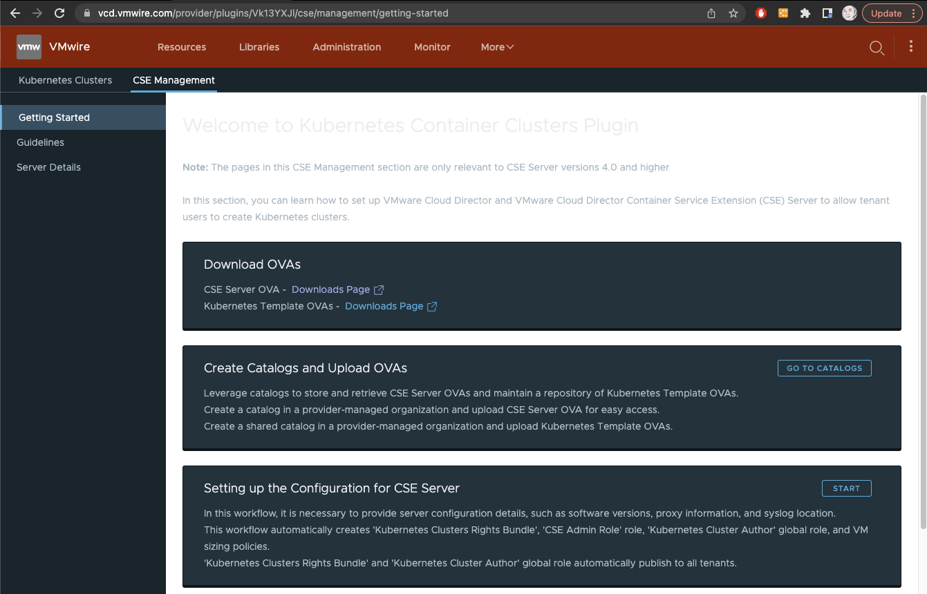
Container Service Extension 4 was released recently. This post aims to help ease the setup of CSE 4.0 as it has a different deployment model using the Solutions framework instead of deploying the CSE appliance into the traditional Management cluster concept used by service providers to run VMware management components such as vCenter, NSX-T Managers, Avi Controllers and other management systems.
Step 1 – Create a CSE Service Account
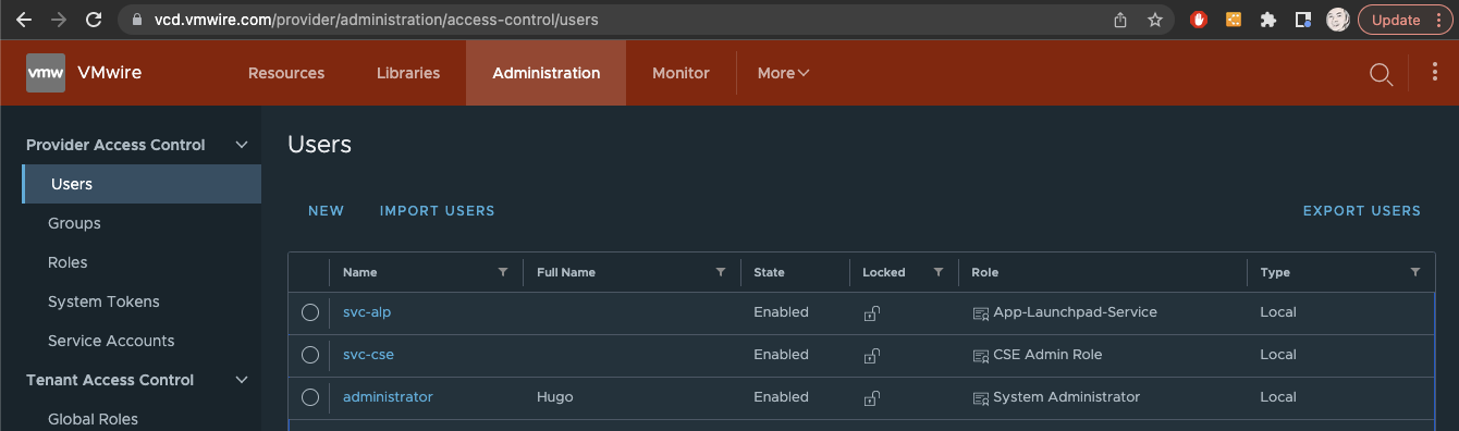
Perform these steps using the administrator@system account or an equivalent system administrator role.
Setup a Service Account in the Provider (system) organization with the role CSE Admin Role.
In my environment I created a user to use as a service account named svc-cse. You’ll notice that this user has been assigned the CSE Admin Role.
The CSE Admin Role is created automatically by CSE when you use the CSE Management UI as a Provider administrator, just do these steps using the administrator@system account.
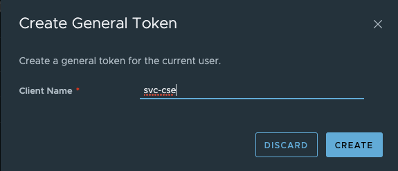
Step 2 – Create a token for the Service Account
Log out of VCD and log back into the Provider organization as the service account you created in Step 1 above. Once logged in, it should look like the following screenshot, notice that the svc-cse user is logged into the Provider organization.
Click on the downward arrow at the top right of the screen, next to the user svc-cse and select User Preferences.
Under Access Tokens, create a new token and copy the token to a safe place. This is what you use to deploy the CSE appliance later.
Log out of VCD and log back in as adminstrator@system to the Provider organization.
Step 3 – Deploy CSE appliance
Create a new tenant Organization where you will run CSE. This new organization is dedicated to VCD extensions such as CSE and is managed by the service provider.
For example you can name this new organization something like “solutions-org“. Create an Org VDC within this organization and also the necessary network infrastructure such as a T1 router and an organization network with internet access.
Still logged into the Provider organization, open another tab by clicking on the Open in Tenant Portal link to your “solutions-org” organization. You must deploy the CSE vApp as a Provider.
Now you can deploy the CSE vApp.
Use the Add vApp From Catalog workflow.
Accept the EULA and continue with the workflow.
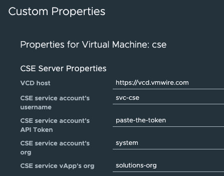
When you get the Step 8 of the Create vApp from Template, ensure that you setup the OVF properties like my screenshot below:
The important thing to note is to ensure that you are using the correct service account username and use the token from Step 2 above.
Also since you must have the service account in the Provider organization, leave the default system organization for CSE service account’s org.
The last value is very important, it must by set to the tenant organization that will run the CSE appliance, in our case it is the “solutions-org” org.
Once the OVA is deployed you can boot it up or if you want to customize the root password then do so before you start the vApp. If not, the default credentials are root and vmware.
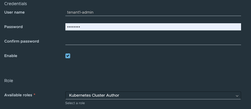
Rights required for deploying TKG clusters
Ensure that the user that is logged into a tenant organization has the correct rights to deploy a TKG cluster. This user must have at a minimum the rights in the Kubernetes Cluster Author Global Role.
App LaunchPad
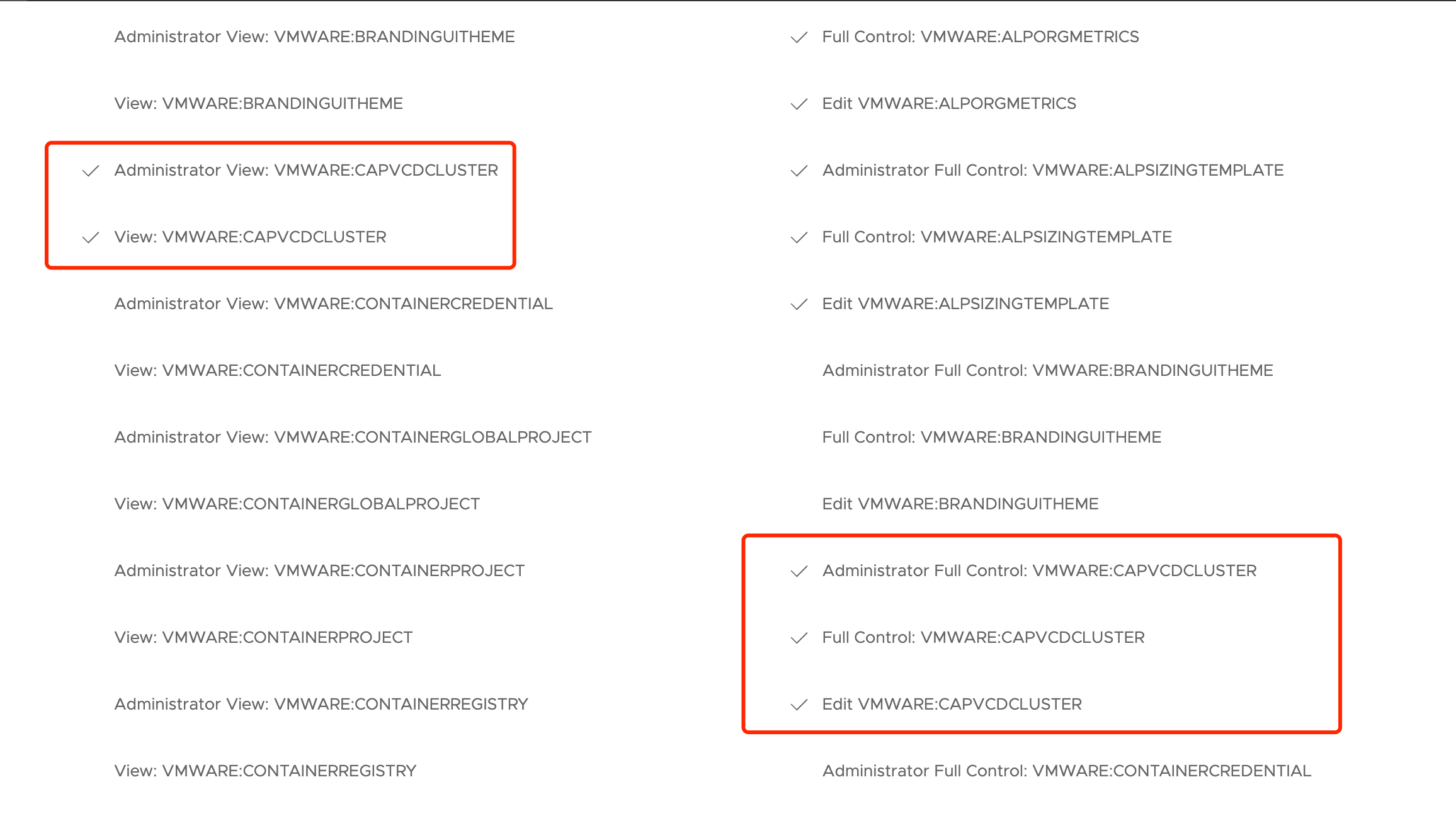
You’ll also need to upgrade App Launchpad to the latest version alp-2.1.2-20764259 to support CSE 4.0 deployed clusters.
Also ensure that the App-Launchpad-Service role has the rights to manage CAPVCD clusters.
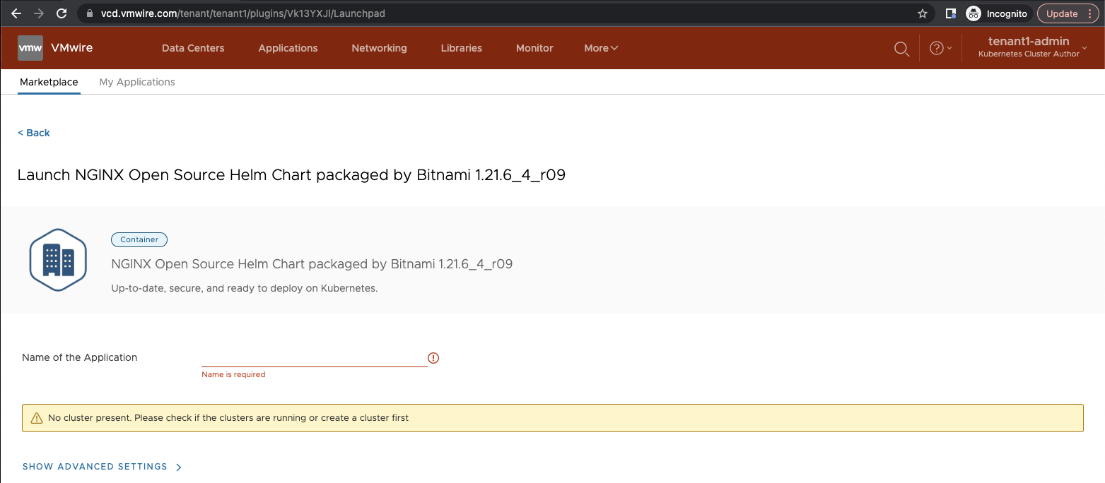
Otherwise you may encounter the following issue:
VCD API Protected by Web Application Firewalls
If you are using a web application firewall (WAF) in front of your VCD cells and you are blocking access to the provider side APIs. You will need to add the SNAT IP address of the T1 from the solutions-org into the WAF whitelist.
The CSE appliance will need access to the VCD provider side APIs.
I wrote about using a WAF in front of VCD in the past to protect provider side APIs. You can read those posts here and here.
For those partners that have been testing the beta, you’ll need to remove all traces of it before you can install the GA version. VMware does not support upgrading or migrating from beta builds to GA builds.
This is a post to help you clean up your VMware Cloud Director environment in preparation for the GA build of CSE 4.0.
For those partners that have been testing the beta, you’ll need to remove all traces of it before you can install the GA version. VMware does not support upgrading or migrating from beta builds to GA builds.
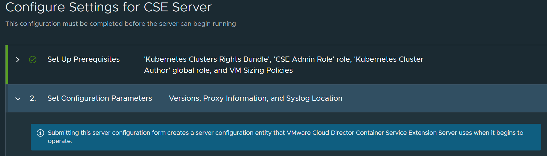
If you don’t clean up, when you try to configure CSE again with the CSE Management wizard, you’ll see the message below:
“Server configuration entity already exists.”
Delete CSE Roles
First delete all the CSE Roles that the beta has setup, the GA version of CSE will recreate these for you when you use the CSE management wizard. Don’t forget to assign the new role to your CSE service account when you deploy the CSE GA OVA.
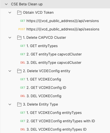
Use the Postman Collection to clean up
I’ve included a Postman collection on my Github account, available here.
Hopefully, it is self-explanatory. Authenticate against the VCD API, then run each API request in order, make sure you obtain the entity and entityType IDs before you delete.
If you’re unable to delete the entity or entityTypes, you may need to delete all of the CSE clusters before, that means cleaning up all PVCs, PVs, deployments and then the clusters themselves.
Deploy CSE GA Normally
You’ll now be able to use the Configure Management wizard and deploy CSE 4.0 GA as normal.
Known Issues
If you’re unable to delete any of these entities then run a POST using /resolve.
For example, https://vcd.vmwire.com/api-explorer/provider#/definedEntity/resolveDefinedEntity
Once, it is resolved, you can go ahead and delete the entity.
Velero (formerly Heptio Ark) gives you tools to back up and restore your Kubernetes cluster resources and persistent volumes. You can run Velero with a cloud provider or on-premises.
This works with any Kubernetes cluster, including Tanzu Kubernetes Grid and Kubernetes clusters deployed with Container Service Extension with VMware Cloud Director.
This solution can be used for air-gapped environments where the Kuberenetes clusters do not have Internet access and cannot use public services such as Amazon S3, or Tanzu Mission Control Data Protection. These services are SaaS services which are pretty much out of bounds in air-gapped environments.
Overview
Velero (formerly Heptio Ark) gives you tools to back up and restore your Kubernetes cluster resources and persistent volumes. You can run Velero with a cloud provider or on-premises. Velero lets you:
Take backups of your cluster and restore in case of loss.
Migrate cluster resources to other clusters.
Replicate your production cluster to development and testing clusters.
Velero consists of:
A server that runs on your Kubernetes cluster
A command-line client that runs locally
Velero works with any Kubernetes cluster, including Tanzu Kubernetes Grid and Kubernetes clusters deployed using Container Service Extension with VMware Cloud Director.
This solution can be used for air-gapped environments where the Kubernetes clusters do not have Internet access and cannot use public services such as Amazon S3, or Tanzu Mission Control Data Protection. These services are SaaS services which are pretty much out of bounds in air-gapped environments.
Install Velero onto your workstation
Download the latest Velero release for your preferred operating system, this is usually where you have your kubectl tools.
If you want to enable bash auto completion, please follow this guide.
Setup an S3 service and bucket
I’m using TrueNAS’ S3 compatible storage in my lab. TrueNAS is an S3 compliant object storage system and is incredibly easy to setup. You can use other S3 compatible object stores such as Amazon S3. A full list of supported providers can be found here.
Follow these instructions to setup S3 on TrueNAS.
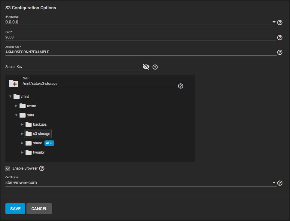
Add certificate, go to System, Certificates
Add, Import Certificate, copy and paste cert.pem and cert.key
Storage, Pools, click on the three dots next to the Pools that will hold the S3 root bucket.
Add a Dataset, give it a name such as s3-storage
Services, S3, click on pencil icon.
Setup like the example below.
Setup the access key and secret key for this configuration.
Update DNS to point to s3.vmwire.com to 10.92.124.20 (IP of TrueNAS). Note that this FQDN and IP address needs to be accessible from the Kubernetes worker nodes. For example, if you are installing Velero onto Kubernetes clusters in VCD, the worker nodes on the Organization network need to be able to route to your S3 service. If you are a service provider, you can place your S3 service on the services network that is accessible by all tenants in VCD.
Setup the connection to your S3 service using the access key and secret key.
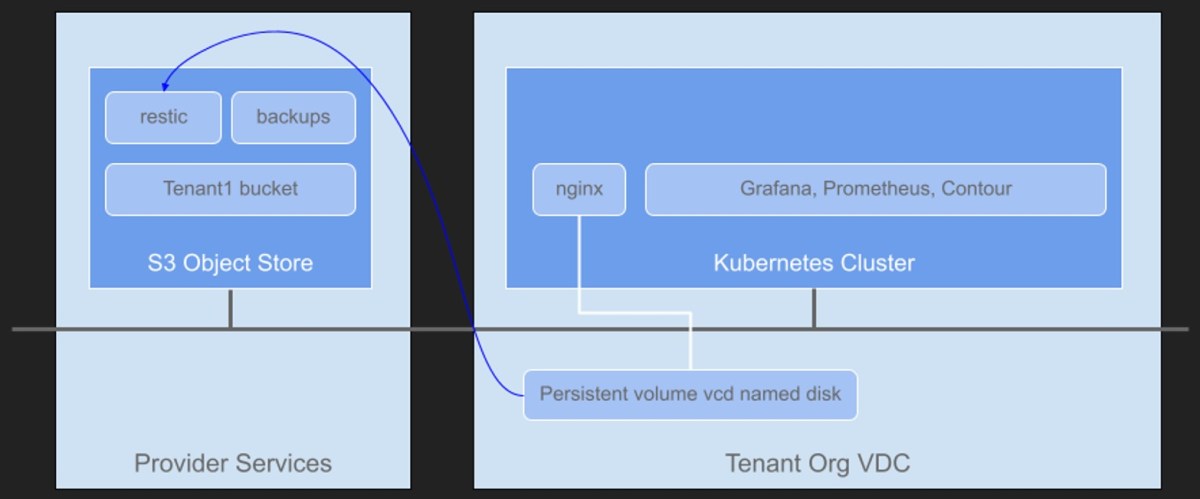
Create a new bucket to store some backups. If you are using Container Service Extension with VCD, create a new bucket for each Tenant organization. This ensures multi-tenancy is maintained. I’ve create a new bucket named tenant1 which corresponds to one of my tenant organizations in my VCD environment.
Install Velero into the Kubernetes cluster
You can use the velero-plugin-for-aws and the AWS provider with any S3 API compatible system, this includes TrueNAS, Cloudian Hyperstore etc.
Setup a file with your access key and secret key details, the file is named credentials-velero.
vi credentials-velero
[default]
aws_access_key_id = AKIAIOSFODNN7EXAMPLE
aws_secret_access_key = wJalrXUtnFEMIK7MDENGbPxRfiCYEXAMPLEKEY
Change your Kubernetes context to the cluster that you want to enable for Velero backups. The Velero CLI will connect to your Kubernetes cluster and deploy all the resources for Velero.
To install Restic, use the --use-restic flag in the velero install command. See the install overview for more details on other flags for the install command.
velero install --use-restic
When using Restic on a storage provider that doesn’t have Velero support for snapshots, the --use-volume-snapshots=false flag prevents an unused VolumeSnapshotLocation from being created on installation. The VCD CSI provider does not provide native snapshot capability, that’s why using Restic is a good option here.
I’ve enabled the default behavior to include all persistent volumes to be included in pod backups enabled on all Velero backups running the velero install command with the --default-volumes-to-restic flag. Refer install overview for details.
Specify the bucket with the --bucket flag, I’m using tenant1 here to correspond to a VCD tenant that will have its own bucket for storing backups in the Kubernetes cluster.
For the --backup-location-config flag, configure you settings like mine, and use the s3Url flag to point to your S3 object store, if you don’t use this Velero will use AWS’ S3 public URIs.
NAME                          READY   STATUS    RESTARTS   AGE
pod/restic-x6r69              1/1     Running   0          49m
pod/velero-7bc4b5cd46-k46hj   1/1     Running   0          49m

NAME                    DESIRED   CURRENT   READY   UP-TO-DATE   AVAILABLE   NODE SELECTOR   AGE
daemonset.apps/restic   1         1         1       1            1           <none>          49m

NAME                     READY   UP-TO-DATE   AVAILABLE   AGE
deployment.apps/velero   1/1     1            1           49m

NAME                                DESIRED   CURRENT   READY   AGE
replicaset.apps/velero-7bc4b5cd46   1         1         1       49m
A quick note on the Rights Bundles for Container Service Extension when enabling native, TKGm or TKGs clusters.
The rights bundle named vmware:tkgcluster Entitlement are for TKGs clusters and NOT for TKGm.
The rights bundle named cse:nativeCluster Entitlement are for native clusters AND also for TKGm clusters.
Yes, this is very confusing and will be fixed in an upcoming release.
You can see a brief note about this on the release notes here.
Users deploying VMware Tanzu Kubernetes Grid clusters should have the rights required to deploy exposed native clusters and additionally the right Full Control: CSE:NATIVECLUSTER. This right is crucial for VCD CPI to work properly.
So in summary, for a user to be able to deploy TKGm clusters they will need to have the cse:nativeCluster Entitlement rights.
To publish these rights, go to the Provider portal and navigate to Administration, Rights Bundles.
Click on the radio button next to cse:nativeCluster Entitlement and click on Publish, then publish to the desired tenant or to all tenants.
This article covers protecting and load balancing the Cloud Director application with Avi Networks. It covers SSL termination. health monitoring and layer 7 HTTP filtering. It can also be used as a reference for other load balancer products such as F5 LTM or NGINX.
Overview
The Avi Vantage platform is built on software-defined principles, enabling a next generation architecture to deliver the flexibility and simplicity expected by IT and lines of business. The Avi Vantage architecture separates the data and control planes to deliver application services beyond load balancing, such as application analytics, predictive autoscaling, micro-segmentation, and self-service for app owners in both on-premises or cloud environments. The platform provides a centrally managed, dynamic pool of load balancing resources on commodity x86 servers, VMs or containers, to deliver granular services close to individual applications. This allows network services to scale near infinitely without the added complexity of managing hundreds of disparate appliances.
Controllers – these are the management appliances that are responsible for state data, Service Engines are deployed by the controllers. The controllers run in a management network.
Service Engines – the load balancing services run in here. These generally run in a DMZ network. Service Engines can have one or more network adaptors connected to multiple networks. At least one network with routing to the controllers, and the remaining networks as data networks.
Deployment modes
Avi can be installed in a variety of deployment types. For VMware Cloud on AWS, it is not currently possible to deploy using ‘write access’ as vCenter is locked-down in VMC and it also has a different API from vSphere 6.7 vCenter Server. You’ll also find that other tools may not work with vCenter in a VMware Cloud on AWS SDDC, such as govc.
Instead Avi needs to be deployed using ‘No Access’ mode.
You can refer to this link for instructions to deploy Avi Controllers in ‘No Access’ mode.
Since it is only possible to use ‘No Access’ mode with VMC based SDDCs, its also a requirement to deploy the service engines manually. To do this follow the guide in this link, and start at the section titled Downloading Avi Service Engine on OVA.
If you’re using Avi with on-premises deployments of vCenter, then ‘Write Mode’ can be used to automate the provisioning of service engines. Refer to this link for more information on the different modes.
Deploying Avi Controller with govc
You can deploy the Avi Controller onto non VMware Cloud on AWS vCenter servers using the govc tool. Refer to this other post on how to do so. I’ve copied the JSON for the controller.ova for your convenience below.
For a high-level architecture overview, this link provides a great starting point.
Figure 1. Avi architecture
Service Engine Typical Deployment Architecture
Generally in legacy deployments, where BGP is not used. The service engines would tend to have three network interfaces. These are typically used for frontend, backend and management networks. This is typical of traditional deployments with F5 LTM for example.
For our example here, I will use three networks for the SEs as laid out below.
Network name
Gateway CIDR
Purpose
sddc-cgw-vcd-dmz1
10.104.125.1/24
Management
sddc-cgw-vcd-dmz2
10.104.126.1/24
Backend
sddc-cgw-vcd-dmz3
10.104.127.1/24
Frontend
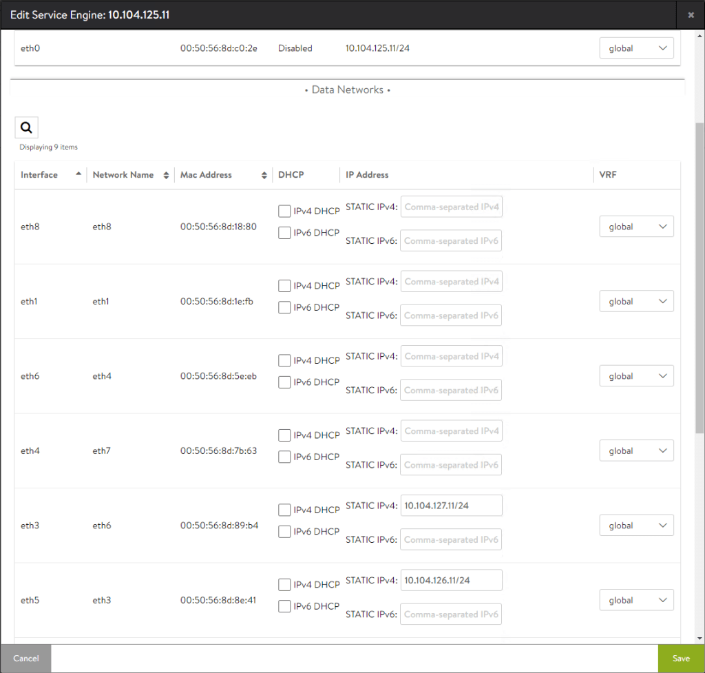
The service engines are configured with the following details. It is important to make a note of the MAC addresses in ‘No access’ mode as you will need this information later.
Service Engine
avi-se1
avi-se2
Management
IP Address 10.104.125.11 Mac Address 00:50:56:8d:c0:2e
IP Address 10.104.125.12 Mac Address 00:50:56:8d:38:33
Backend
IP Address 10.104.126.11 Mac Address 00:50:56:8d:8e:41
IP Address 10.104.126.12 Mac Address 00:50:56:8d:53:f6
Frontend
IP Address 10.104.127.11 Mac Address 00:50:56:8d:89:b4
IP Address 10.104.127.12 Mac Address 00:50:56:8d:80:41
The Management network is used for communications between the SEs and the Avi controllers. For the port requirements, please refer to this link.
The Backend network is used for communications between the SEs and the application that is being load balanced and protected by Avi.
The Frontend network is used for upstream communications to the clients, in this case the northbound router or firewall towards the Internet.
Sample Application
Lets use VMware Cloud Director as the sample application for configuring Avi. vCD as it is more commonly named (to be renamed VMware Cloud Director), is a cloud platform which is deployed with an Internet facing portal. Due to this, it is always best to protect the portal from malicious attacks by employing a number of methods.
Some of these include, SSL termination and web application filtering. The following two documents explain this in more detail.
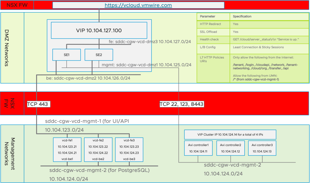
You’ll notice that the eth0 and eth1 interfaces are connected to two different management networks 10.104.123.0/24 and 10.104.124.0/24 respectively. For vCD, it is generally good practice to separate the two interfaces into separate networks.
Network name
Gateway CIDR
Purpose
sddc-cgw-vcd-mgmt-1
10.104.123.1/24
vCD Frontend UI/API/VM Remote Console
sddc-cgw-vcd-mgmt-2
10.104.124.1/24
vCD Backend PostgreSQL, SSH etc.
For simplicity, I also deployed my Avi controllers onto the sddc-cgw-vcd-mgmt-2 network.
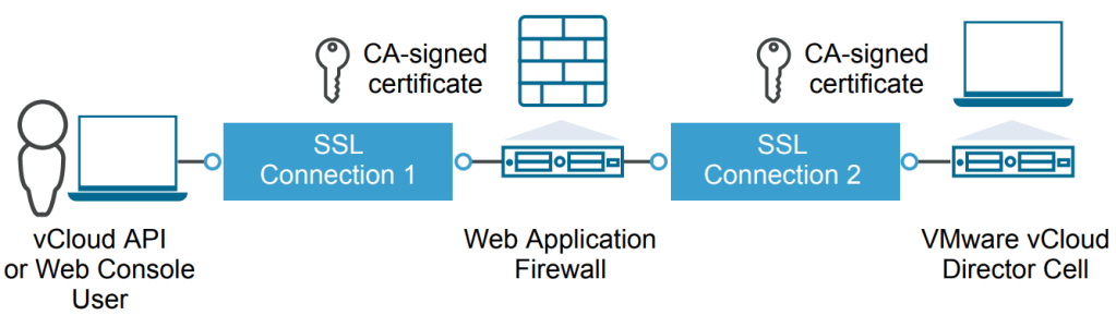
The diagram below summarises the above architecture for the HTTP interface for vCD. For this guide, I’ve used VMware Cloud on AWS together with Avi Networks to protect vCD running as an appliance inside the SDDC. This is not a typical deployment model as Cloud Director Service will be able to use VMware Cloud on AWS SDDC resource soon, but I wanted to showcase the possibilities and constraints when using Avi with VMC based SDDCs.
Figure 2 . vCD HTTP Diagram
Configuring Avi for Cloud Director
After you have deployed the Avi Controllers and the Service Engines, there are few more steps needed before vCD is fully up and operational. The proceeding steps can be summarised as follows:
Setup networking for the service engines by assigning the right IP address to the correct MAC addresses for the data networks
Configure the network subnets for the service engines
Configure static routes for the service engines to reach vCD
Setup Legacy HA mode for the service engine group
Setup the SSL certificate for the HTTP service
Setup the Virtual Services for HTTP and Remote Console (VMRC)
Setup the server pools
Setup health monitors
Setup HTTP security policies
Map Service Engine interfaces
Using the Avi Vantage Controller, navigate to Infrastructure > Service Engine, select one of the Service Engines then click on the little pencil icon. Then map the MAC addresses to the correct IP addresses.
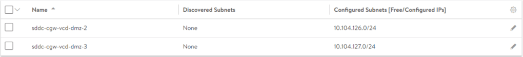
Configure the network subnets for the service engines
Navigate to Infrastructure > Networks and create the subnets.
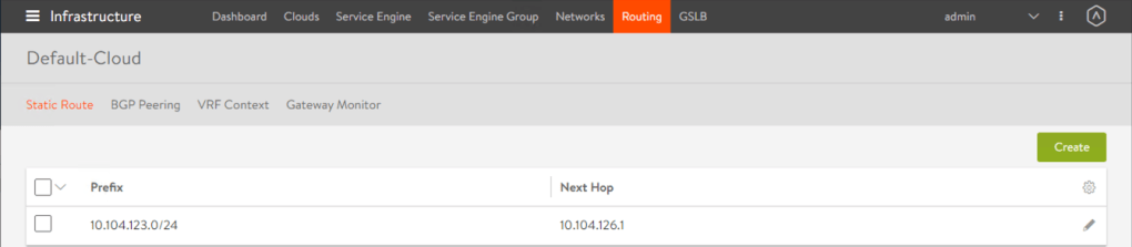
Configure static routes
Navigate to Infrastructure > Routing and setup any static routes. You’ll notice from figure 2 that since the service engine has three network interfaces on different networks, we need to create a static route on the interface that does not have the default gateway. This is so the service engines knows which gateway to use to route traffic for particular traffic types. In this case, the gateway for the service engine to route the HTTP and Remote Console traffic southbound to the vCD cells.
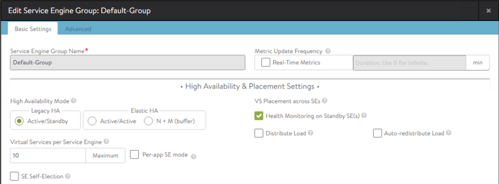
Setup Legacy HA mode for the service engine group
Navigate to Infrastructure > Service Engine Group.
Setup the HA mode to Legacy HA. This is the simplest configuration, you can use Elastic HA if you wish.
Configure the HTTP and Remote Console Virtual Services
Navigate to Applications > Virtual Services.
Creating a Virtual Service, has a few sub tasks which include the creation of the downstream server pools and SSL certificates.
Create a new Virtual Service for the HTTP service, this is for the Cloud Director UI and API. Please use this example to create another Virtual Service for the Remote Console.
For the Remote Console service, you will need to accept TCP 443 on the load balancer but connect southbound to the Cloud Director appliances on port TCP 8443. TCP 8443 is the port that VMRC uses as it shares the same IP addresses as the HTTP service.
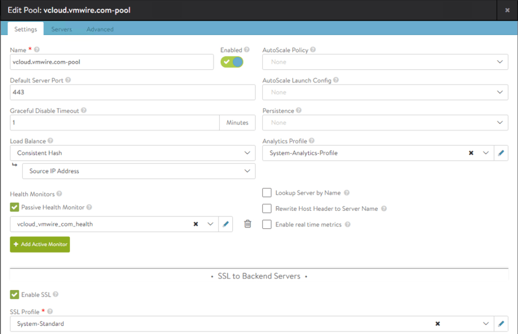
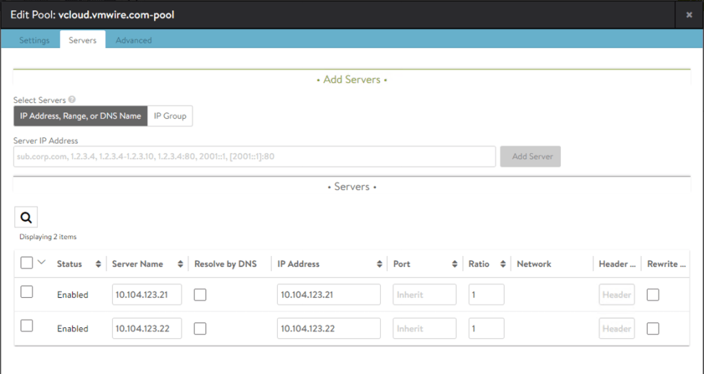
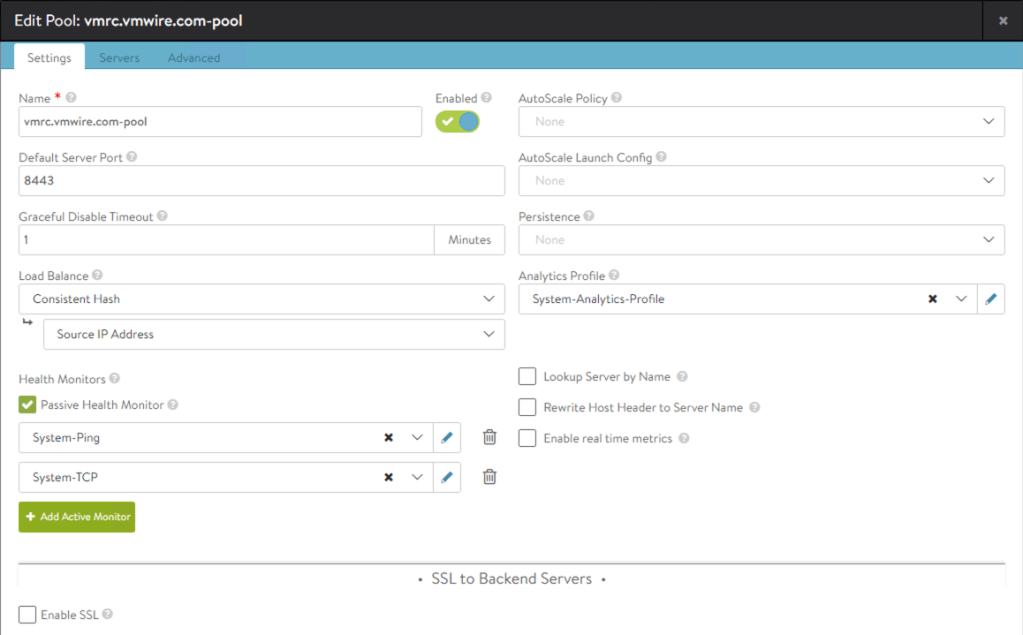
You may notice that the screenshot is for an already configured Virtual Service for the vCD HTTP service. The server pool and SSL certificate is already configured. Below are the screenshots for those.
Certificate Management
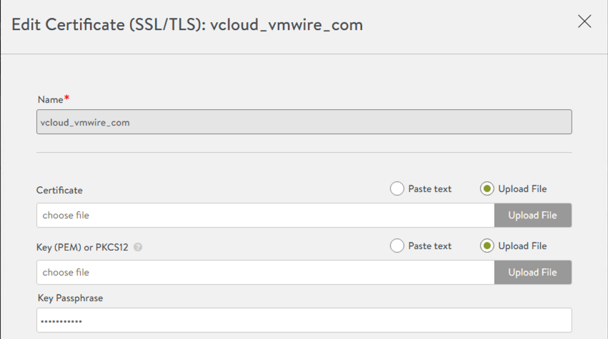
You may already have a signed HTTP certificate that you wish to use with the load balancer for SSL termination. To do so, you will need to use the JAVA keytool to manipulate the HTTP certificate, obtaining the private key and convert from JCEKS to PCKS12. JAVA keytool is available in the vCD appliance at /opt/vmware/vcloud-director/jre/bin/.
Figure 3. SSL termination on load balancer
For detailed instructions on creating a signed certificate for vCD, please follow this guide.
Convert the keystore file certificates.ks file from JCEKS to PKCS12
Now that you have the private key for the HTTP certificate, you can go ahead and configure the HTTP certificate on the load balancer.
For the certificate file, you can either paste the text or upload the certificate file (.cer, .crt) from the certificate authority for the HTTP certificate.
For the Key (PEM) or PKCS12 file, you can use the httpcert.p12 file that you extracted from the certificates_pkcs12.ks file above.
The Key Passphrase is the password that you used to secure the httpcert.p12 file earlier.
Note that the vCD Remote Console (VMRC) must use pass-through for SSL termination, e.g., termination of the VMRC session must happen on the Cloud Director cell. Therefore, the above certificate management activities on Avi are not required for the VMRC.
Health Monitors
Navigate to Applications > Pools.
Edit the HTTP pool using the pencil icon and click on the Add Active Monitor green button.
Health monitoring of the HTTP service uses
GET /cloud/server_status HTTP/1.0
With an expected server response of
Service is up.
And a response code of 200.
The vCD Remote Console Health monitor is a lot simpler as you can see below.
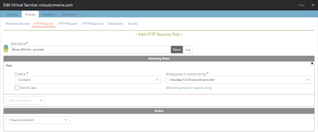
Layer 7 HTTP Security
Layer 7 HTTP Security is very important and is highly recommended for any application exposed to the Internet. Layer 3 fire-walling and SSL certificates is always never enough in protecting and securing applications.
Navigate to Applications > Virtual Services.
Click on the pencil icon for the HTTP virtual service and then click on the Policies tab. Then click on the HTTP Security policy. Add a new policy with the following settings. You can read more about Layer 7 HTTP policies here.
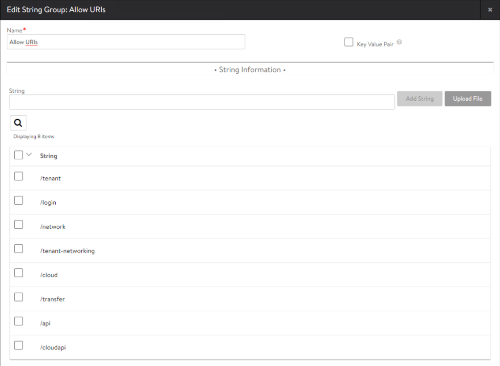
Allowed Strings
Required by
/tenant
Tenant use
/login
Login
/network
Access to networking
/tenant-networking
Access to networking
/cloud
For SAML/SSO logins
/transfer
Uploads/Downloads of ISO and templates
/api
General API access
/cloudapi
General API access
/docs
Swagger API browser
Blocked Strings
/cloudapi/1.0.0/sessions/provider
Specifically block admin APIs from the Internet
This will drop all provider side services when accessed from the Internet. To access provider side services, such as /provider or admin APIs, use an internal connection to the Cloud Director cells.
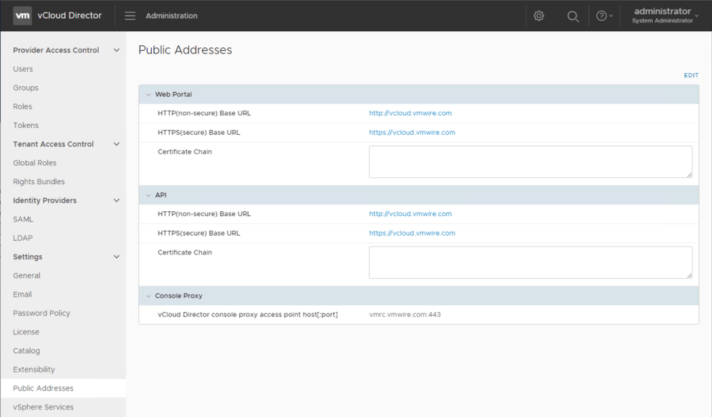
Change Cloud Director public addresses
If not already done so, you should also change the public address settings in Cloud Director.