This post is an update to enable the automated installation of Container Service Extension to version 3.1.2, the script is also updated for better efficiency.
This post is an update to enable the automated installation of Container Service Extension to version 3.1.2, the script is also updated for better efficiency.
You can find the details on my github account under the repository named cse-automated.
Ensure you review the README.MD and read the comments in the script too.
Pre-Requisites
Deploy Photon OVA into vSphere, 2 VCPUs, 4GB RAM is more than enough
Assign VM a hostname and static IP
Ensure it can reach the Internet
Ensure it can also reach VCD on TCP 443 and vCenter servers registered in VCD on TCP 443.
SSH into the Photon VM
Note that my environment has CA signed SSL certs and the script has been tested against this environment. I have not tested the script in environments with self-signed certificates.
Download cse-install.sh script to Photon VM
# Download the script to the Photon VM
curl https://raw.githubusercontent.com/hugopow/cse-automated/main/cse-install.sh --output cse-install.sh

#  Make script executable
chmod +x cse-install.sh
Change the cse-install.sh script
Make sure you change passwords, CA SSL certificates and environment variables to suit your environment.
Launch the script, sit back and relax
# Run as root
sh cse-install.sh
Demo Video
Old video of CSE 3.0.4 automated install, but still the same process.
VMware Cloud Director App Launchpad allows users to deploy applications from public and private registries very easily into their VCD clouds, either as virtual machines or as containers into Kubernetes clusters provisioned into VCD by Container Service Extension.
Installing ALP requires a Linux system, followed by installing the application from an RPM file and then going through some configuration commands to connect ALP to the VCD system. Tedious at best and prone to errors.
This post shows how you can run ALP as a Kubernetes pod in a Kubernetes cluster instead of running ALP in a VM.
Disclaimer: This is unsupported. This post is an example of how you can run App Launchpad in Kubernetes instead of deploying it on a traditional VM. Use at your own risk. Please continue to run ALP in supported configurations in production environments.
VMware Cloud Director App Launchpad allows users to deploy applications from public and private registries very easily into their VCD clouds, either as virtual machines or as containers into Kubernetes clusters provisioned into VCD by Container Service Extension.
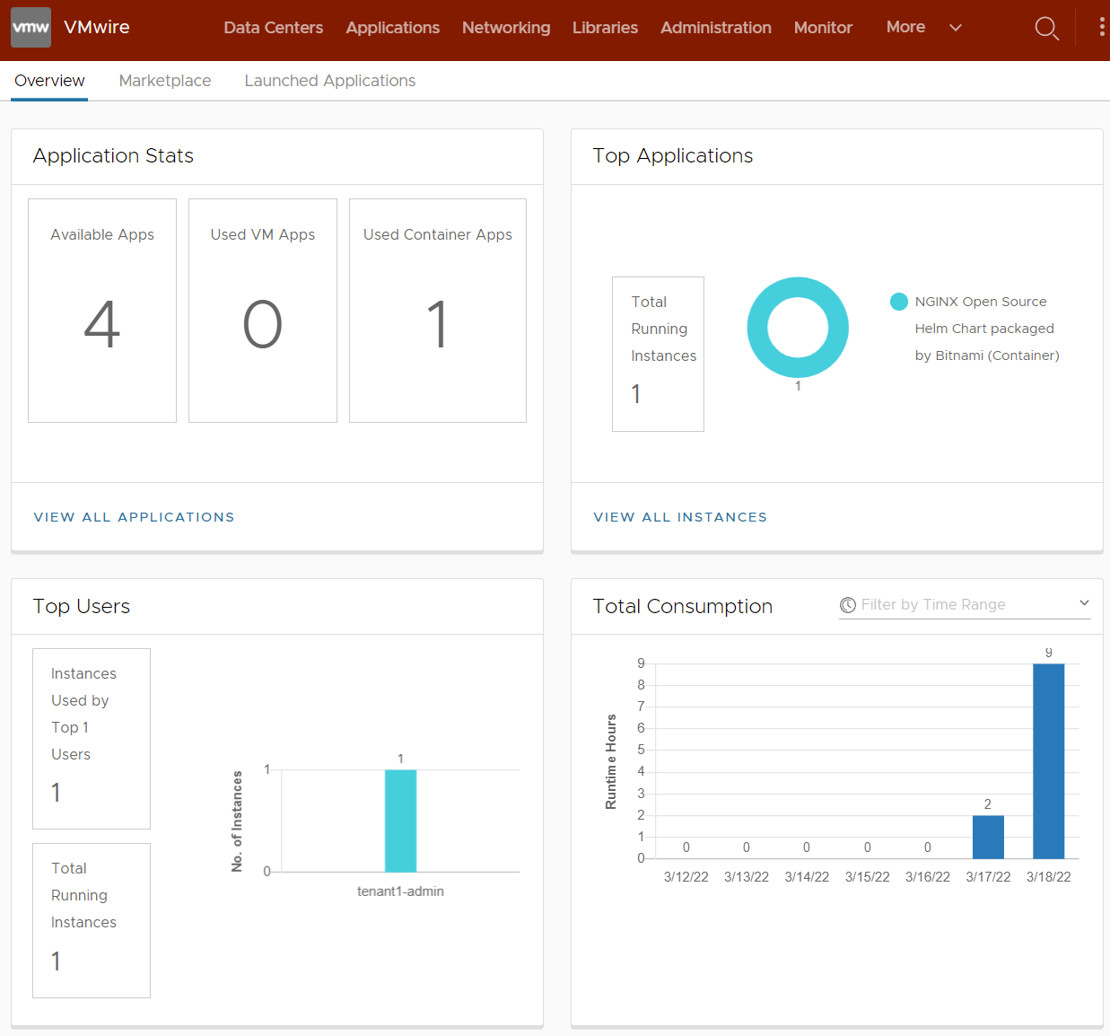
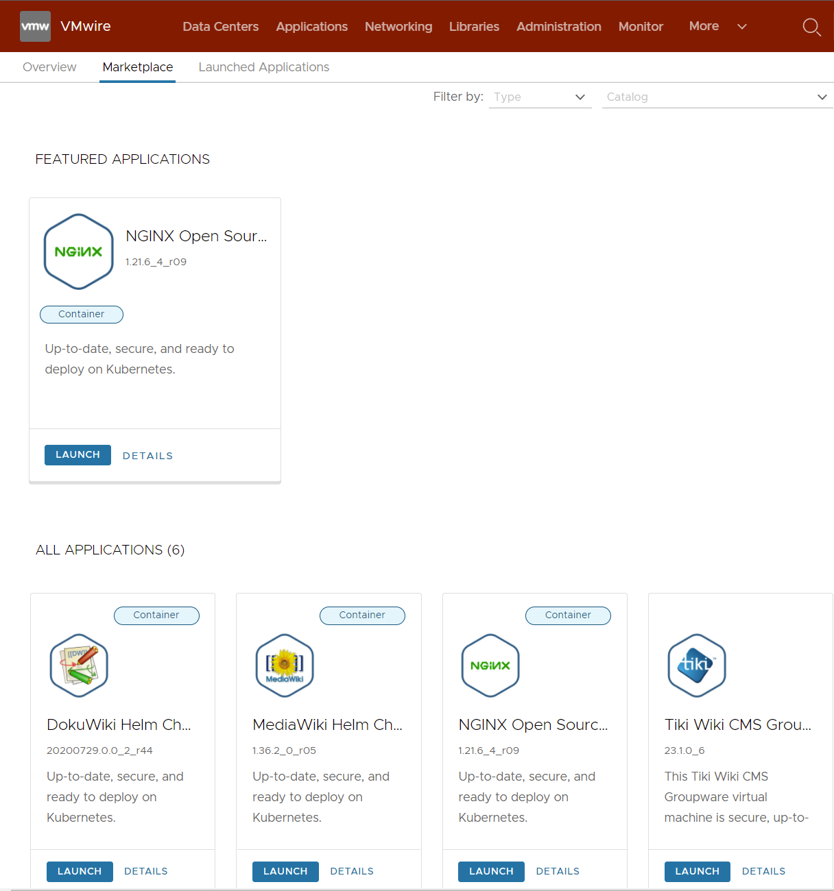
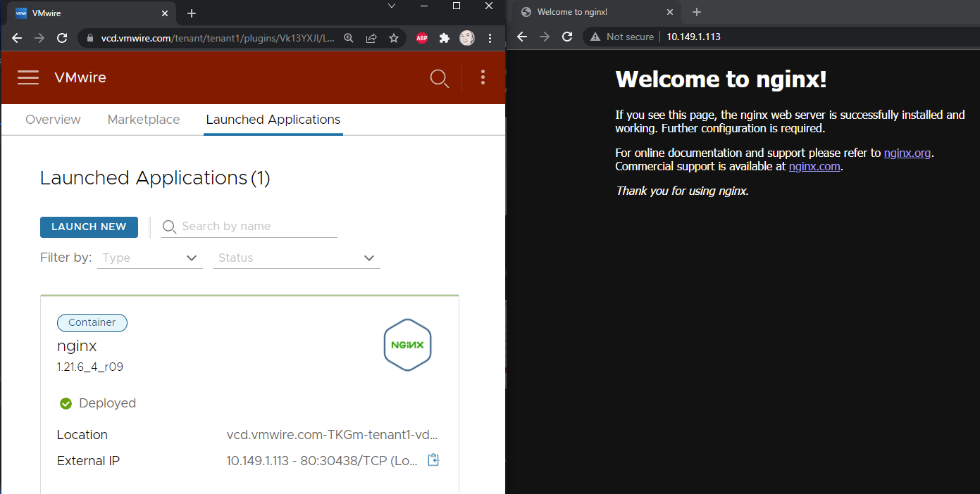
Here are a few screenshots of ALP in action in VCD.
How is App Launchpad Installed in a VM?
Installing ALP requires a Linux system, followed by installing the application from an RPM file and then going through some configuration commands to connect ALP to the VCD system. Tedious at best and prone to errors.
This post shows how you can run ALP as a Kubernetes pod in a Kubernetes cluster instead of running ALP in a VM.
Disclaimer: This is unsupported. This post is an example of how you can run App Launchpad in Kubernetes instead of deploying it on a traditional VM. Use at your own risk. Please continue to run ALP in supported configurations in production environments.
VMs vs Containers
Running containers in Kubernetes instead of VMs provides enhanced benefits. Such as:
Containers are more lightweight than VMs, as their images are measured in megabytes rather than gigabytes
Containers require fewer IT resources to deploy, run, and manage
Containers spin up in milliseconds
Since their order of magnitude is smaller, a single system can host many more containers as compared to VMs
Containers are easier to deploy and fit in well with infrastructure as code concepts
Developing, testing, running and managing applications are easier and more efficient with containers.
You’ll find the values.yaml file in the /app-launchpad directory. Edit it to your liking and also accept the ALP EULA, you’ll also find the EULA in the README.md file.
alpConnect:
  saUser: "svc-alp"
  saPass: Vmware1!
  url: https://vcd.vmwire.com
  adminUser: administrator@system
  adminPass: Vmware1!
  mqtt: true
  eula: accept
# If you accept the EULA then type "accept" in the EULA key value to install ALP.
You can either package the chart and place it into your own registry or just use mine.
values.yaml
NAME: app-launchpad
LAST DEPLOYED: Fri Mar 18 09:54:16 2022
NAMESPACE: app-launchpad
STATUS: deployed
REVISION: 1
TEST SUITE: None
Running the following command will show that the deployment is successful
helm list -n app-launchpad
NAME            NAMESPACE       REVISION        UPDATED                                 STATUS          CHART                   APP VERSION
app-launchpad   app-launchpad   1               2022-03-18 09:54:16.560871812 +0000 UTC deployed        app-launchpad-0.4.0     2.1.1
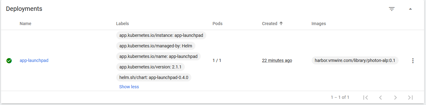
Running the following commands you’ll see that the pod has started
kubectl get deploy -n app-launchpad
NAME            READY   UP-TO-DATE   AVAILABLE   AGE
app-launchpad   1/1     1            1           25m
kubectl get po -n app-launchpad
NAME                             READY   STATUS    RESTARTS   AGE
app-launchpad-669786b6dd-p8fjw   1/1     Running   0          25m
Uninstalling...
Removed /etc/systemd/system/multi-user.target.wants/alp.service.
Removed /etc/systemd/system/multi-user.target.wants/alp-deployer.service.
System has not been booted with systemd as init system (PID 1). Can't operate.
Failed to connect to bus: Host is down
System has not been booted with systemd as init system (PID 1). Can't operate.
Failed to connect to bus: Host is down
warning: %postun(vmware-alp-2.1.1-19234432.x86_64) scriptlet failed, exit status 1
warning: /home/vmware-alp-2.1.1-19234432.ph3.x86_64.rpm: Header V3 RSA/SHA1 Signature, key ID 001e5cc9: NOKEY
Verifying...                          ########################################
Preparing...                          ########################################
Updating / installing...
vmware-alp-2.1.1-19234432             ########################################
New installing...
Found the /opt/vmware/alp/log, change log directory owner and permission ...
chmod: /opt/vmware/alp/log/*: No such file or directory
chown: /opt/vmware/alp/log/*: No such file or directory
Created symlink /etc/systemd/system/multi-user.target.wants/alp.service → /lib/systemd/system/alp.service.
Created symlink /etc/systemd/system/multi-user.target.wants/alp-deployer.service → /lib/systemd/system/alp-deployer.service.
Setup ALP connections
VMWARE END USER LICENSE AGREEMENT
Last updated: 03 May 2021
--- snipped ---
Cloud Director Setting for App Launchpad
+--------------------------------+-----------------------------------------------+
|             Cloud Director URL | https://vcd.vmwire.com                        |
|  App Launchpad Service Account | svc-alp                                       |
| App Launchpad Service Password | Vmware1!                                      |
|                   MQTT Triplet | VMware/AppLaunchpad/1.0.0                     |
|                     MQTT Token | e089774e-389c-4e12-82d0-11378a30981d          |
|          MQTT Topic of Monitor | topic/extension/VMware/AppLaunchpad/1.0.0/ext |
|         MQTT Topic of Response | topic/extension/VMware/AppLaunchpad/1.0.0/vcd |
|   App Launchpad extension UUID | 9ba4f6c8-a1e4-3a57-bd4c-e5ca5c2f8375          |
+--------------------------------+-----------------------------------------------+
Successfully connected and configured with Cloud Director for App Launchpad.
start ALP Deployer service
Start ALP service
==> /opt/vmware/alp/deployer/log/deployer/default.log <==
{"level":"info","timestamp":"2022-03-18T09:54:24.446Z","caller":"cmd/deployer.go:68","msg":"Starting server","Config":{"ALP":{"System":{"Deployer":{"AuthToken":"***"}},"VCDEndpoint":{"URL":"https://vcd.vmwire.com","FingerprintsSHA256":"f4:e0:1b:7c:9c:d2:da:15:94:52:58:6f:80:02:2a:46:8f:ab:a5:91:d7:43:f6:8b:85:60:23:16:93:8b:2a:87"},"Deployer":{"Host":"127.0.0.1","Port":8087,"KubeRESTClient":{"QPS":256,"Burst":512,"Timeout":180000,"CertificateValidation":false},"ChartCacheSize":128}},"Logging":{"Stdout":false,"File":{"Path":"log/deployer/"},"Level":{"Com":{"VMware":{"ALP":"INFO"}}}}}}
{"level":"info","timestamp":"2022-03-18T09:54:24.550Z","caller":"server/manager.go:59","msg":"The manager is starting mux-router"}
 __     __  __  __  __        __     _      ____    _____            _      _       ____
 \ \   / / |  \/  | \ \      / /    / \    |  _ \  | ____|          / \    | |     |  _ \
  \ \ / /  | |\/| |  \ \ /\ / /    / _ \   | |_) | |  _|           / _ \   | |     | |_) |
   \ V /   | |  | |   \ V  V /    / ___ \  |  _ <  | |___         / ___ \  | |___  |  __/
    \_/          \_/\_/    /_/   \_\  \_\ |_____|       /_/   \_\ |_____|

  :: Spring Boot Version : 2.4.13
  :: VMware vCloud Director App LaunchPad Version : 2.1.1-19234432, Build Date: Thu Jan 20 02:18:37 GMT 2022
=================================================================================================================
What next?
It will take around two minutes until ALP is ready.
Open the VCD provider portal and click on the More menu to open up App Launchpad.
From here you can configure App Launchpad and enjoy using the app in a container running in a Kubernetes cluster.
Some other details
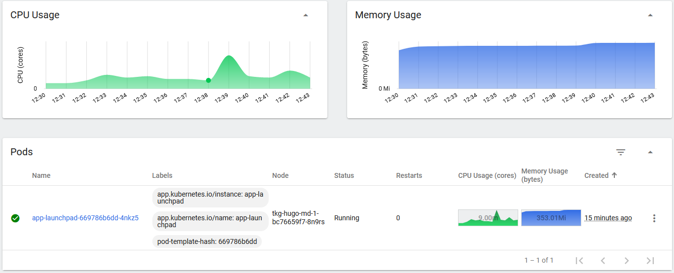
You’ll notice (if you deployed Kubernetes Dashboard), that the pod uses minimal resources after it has started and settled down to an idle state.
Using pretty much no CPU and around 300Mb of memory. This is so much better than running this thing in a VM right?
Note that I have used MQTT for the message bus between ALP and VCD. If you use RabbitMQ, you can in fact deploy multiple pods of ALP and enable Kubernetes to run ALP as a clustered service. MQTT does not support multiple instances of ALP.
Just change the replicaCount value from 1 to 2, and also edit the configMap to change from MQTT to RabbitMQ.
To finish off
I’ve found that moving my lab applications such as ALP and Container Service Extension to Kubernetes has freed up a lot of memory and CPU. This is the main use case for me as I run a lot of labs and demo environments. It is also just a lot easier to deploy these applications with Helm into Kubernetes than using virtual machines.
This is just one example of modernizing some of the VCPP applications to take advantage of the benefits of running in Kubernetes.
I hope this helps you too. Feel free to comment below if you find this useful. I am also working on improving my Container Service Extension Helm chart and will publish that when it is ready.
Working with files in Linux can be a pain, especially when you want to add spaces (yaml files) or multiple spaces to large block of text (certificates). This post shows you how to do just that.
Working with files in Linux can be a pain, especially when you want to add spaces (yaml files) or multiple spaces to large block of text (certificates). This post shows you how to do just that.
The below can be used to add spaces into yaml files very easily. Very useful when adding spaces to tls.crt files for example.
Run this command to add line numbers
:set number
Add four spaces from line 8 to line 37, note that between the last / and the preceding / there are four spaces :3,37s/^/ /
Feature gates are a set of key=value pairs that describe Kubernetes features. You can turn these features on or off using the a ytt overlay file or by editing KubeadmControlPlane or VSphereMachineTemplate. This post, shows you how to enable a feature gate by enabling the MixedProtocolLBService to the TKG kube-apiserver. It can be used to enable other feature gates as well, however, I am using the MixedProtocolLBService to test this at one of my customers.
Feature gates are a set of key=value pairs that describe Kubernetes features. You can turn these features on or off using the a ytt overlay file or by editing KubeadmControlPlane or VSphereMachineTemplate. This post, shows you how to enable a feature gate by enabling the MixedProtocolLBService to the TKG kube-apiserver. It can be used to enable other feature gates as well, however, I am using the MixedProtocolLBService to test this at one of my customers.
Note that enabling feature gates on TKG clusters is unsupported.
The customer has a requirement to test mixed protocols in the same load balancer service (multiple ports and protocols on the same load balancer IP address). This feature is currently in alpha and getting a head start on alpha features is always a good thing to do to stay ahead.
For example to do this in a LoadBalancer service (with the MixedProtocolLBService feature gate enabled):
Let’s assume that you want to enable this feature gate before deploying a new TKG cluster. I’ll show you how to enable this on an existing cluster further down the post.
Greenfield – before creating a new TKG cluster
Create a new overlay file named kube-apiserver-feature-gates.yaml. Place this file in your ~/.config/tanzu/tkg/providers/infrastructure-vsphere/ytt/ directory. For more information on ytt overlays, please read this link.
#! Please add any overlays specific to vSphere provider under this file.

#@ load("@ytt:overlay", "overlay")
#@ load("@ytt:data", "data")

#! Enable MixedProtocolLBService feature gate on kube api.
#@overlay/match by=overlay.subset({"kind":"KubeadmControlPlane"})
---
spec:
  kubeadmConfigSpec:
    clusterConfiguration:
      apiServer:
        extraArgs:
          #@overlay/match missing_ok=True
          feature-gates: MixedProtocolLBService=true
Deploy the TKG cluster.
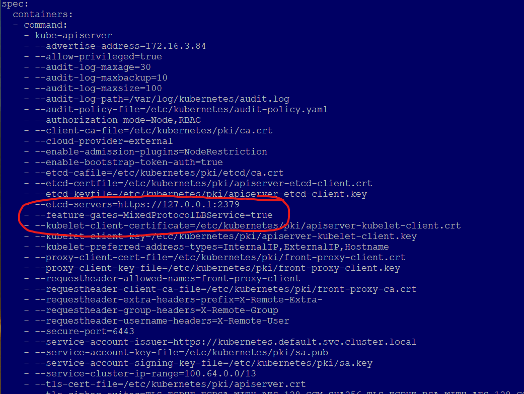
Inspect the kube-apiserver pod for feature gate
k get po -n kube-system kube-apiserver-tkg-test-control-plane-##### -o yaml
You should see on line 44 that the overlay has enabled the feature gate.
Inspect kubeadmcontrolplane, this is the control plane template for the master node, and all subsequent master nodes that are deployed. You can see on line 32, that the feature gate flag is enabled.
k get kubeadmcontrolplane tkg-test-control-plane -o yaml
Now if you created a service with mixed protocols, the kube-apiserver will accept the service and will tell the load balancer to deploy the service.
Brownfield – enable feature gates on an existing cluster
Enabling feature gates on an already deployed cluster is a little bit harder to do, as you need to be extra careful that you don’t break your current cluster.
Let’s edit the KubeadmControlPlane template, you need to do this in the tkg-mgmt cluster context
You’ll see that TKG has immediately started to clone a new control plane VM. Wait for the new VM to replace the current one.
If you inspect the new control plane VM, you’ll see that it has the feature gate applied. You need to do this in the worker cluster context that you want the feature gate enabled on, in my case tkg-hugo.
Note that enabling the feature gate to spec.kubeadmconfigspec.clusterconfiguration.apiserver.extraargs actually, enables the feature gate on the kube-apiserver, which in TKG runs in a pod.
kubectl config use-context tkg-hugo-admin@tkg-hugo
k get po kube-apiserver-tkg-hugo-control-plane-#### -n kube-system -o yaml
Go to the line spec.containers.command.kubeapiserver. You’ll see something like the following:
In the previous post, I described how to install Harbor using Helm to utilize ChartMuseum for running Harbor as a Helm chart repository.
The Harbor registry that comes shipped with TKG 1.5.1 uses Tanzu Packages to deploy Harbor into a TKG cluster. This version of Harbor does not support Helm Charts using ChartMuseum. VMware dropped support for ChartMuseum in TKG and are adopting OCI registries instead. This post describes how to deploy Harbor using the Tanzu Packages (KApp) and use Harbor as an OCI registry that fully supports Helm charts. This is the preferred way to use chart and image registries.
The latest versions as of TKG 1.5.1 packages, February 2022.
Package
Version
cert-manager
1.5.3+vmware.2-tkg.1
contour
1.18.2+vmware.1-tkg.1
harbor
2.3.3+vmware.1-tkg.1
Or run the following to see the latest available versions.
tanzu package available list harbor.tanzu.vmware.com -A
Pre-requisites
Before installing Harbor, you need to install Cert Manager and Contour. You can follow this other guide here to get started. This post uses Ingress, which requires NSX Advanced Load Balancer (Avi). The previous post will show you how to install these pre-requisites.
Deploy Harbor
Create a configuration file named harbor-data-values.yaml. This file configures the Harbor package. Follow the steps below to obtain a template file.
Specify other settings in the harbor-data-values.yaml file.
Set the hostname setting to the hostname you want to use to access Harbor via ingress. For example, harbor.yourdomain.com.
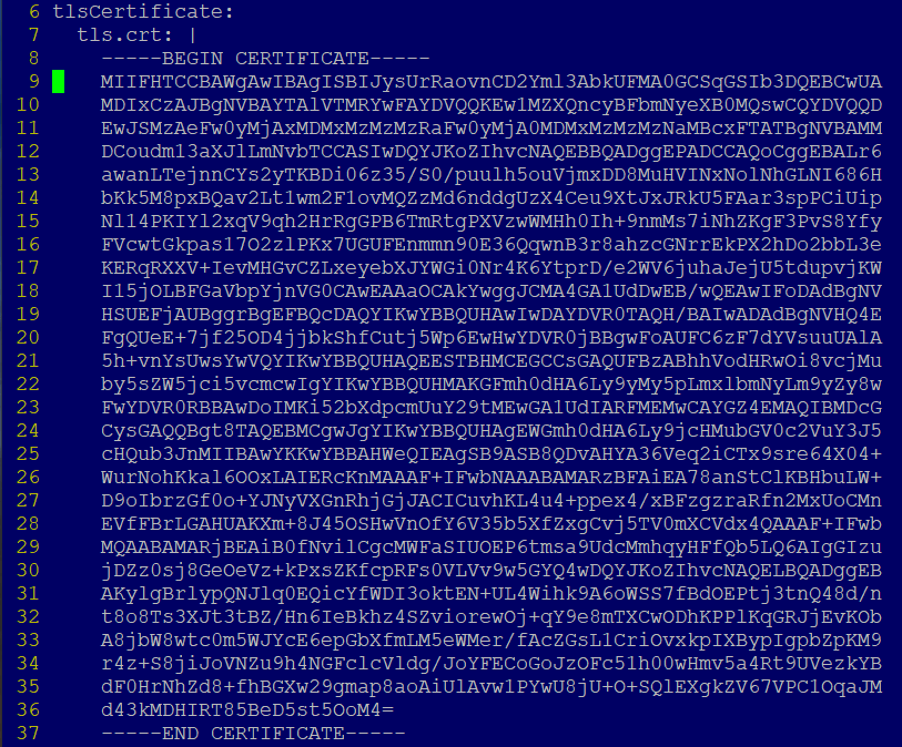
To use your own certificates, update the tls.crt, tls.key, and ca.crt settings with the contents of your certificate, key, and CA certificate. The certificate can be signed by a trusted authority or be self-signed. If you leave these blank, Tanzu Kubernetes Grid automatically generates a self-signed certificate.
The format of the tls.crt and tls.key looks like this:
Obtain the address of the Envoy service load balancer.
kubectl get svc envoy -n tanzu-system-ingress -o jsonpath='{.status.loadBalancer.ingress[0]}'
Update your DNS record to point the hostname to the IP address above.
Update Harbor
Update the Harbor installation in any way, such as updating the TLS certificate, make your changes to the harbor-data-values.yaml file then run the following to update Harbor.
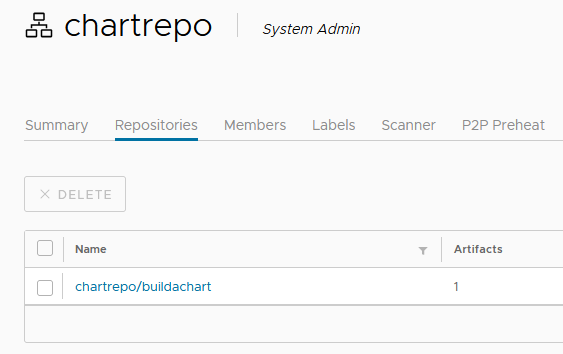
The chart can now be seen in the Harbor UI in the view as where normal Docker images are.
OCI based Harbor
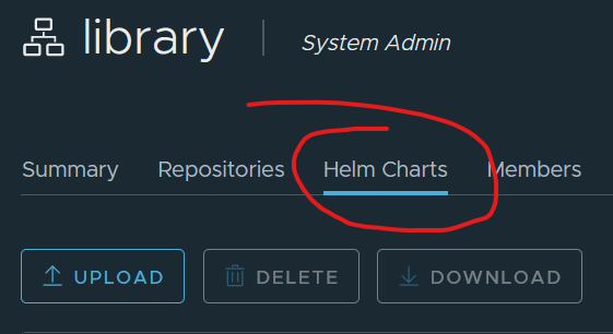
Notice that this is an OCI registry and not a Helm repository that is based on ChartMuseum, thats why you won’t see the ‘Helm Charts’ tab next to the ‘Repositories’ tab.
ChartMuseum based Harbor
Deploy an application with Helm
Let’s deploy the buildachart application, this is a simple nginx application that can use TLS so we have a secure site with HTTPS.
Create a new namespace and the TLS secret for the application. Copy the tls.crt and tls.key files in pem format to $HOME/certs/
# Create a new namespace for cherry
k create ns cherry

# Create a TLS secret with the contents of tls.key and tls.crt in the cherry namespace
kubectl create secret tls cherry-tls --key $HOME/certs/tls.key --cert $HOME/certs/tls.crt -n cherry
Deploy the app using Harbor as the Helm chart repository
The Harbor registry that comes shipped with TKG 1.5.1 uses Tanzu Packages to deploy Harbor into a TKG cluster. This version of Harbor does not support Helm Charts using ChartMuseum. VMware dropped support for ChartMuseum in TKG and are adopting OCI registries instead. This post describes how to deploy the upstream Harbor distribution that supports ChartMuseum for a helm repository. Follow this other post here to deploy Harbor with Tanzu Packages (Kapp) with support for OCI.
Intro
The Harbor registry that comes shipped with TKG 1.5.1 uses Tanzu Packages to deploy Harbor into a TKG cluster. This version of Harbor does not support Helm Charts using ChartMuseum. VMware dropped support for ChartMuseum in TKG and are adopting OCI registries instead. This post describes how to deploy the upstream Harbor distribution that supports ChartMuseum for a helm repository. Follow this other post here to deploy Harbor with Tanzu Packages (Kapp) with support for OCI.
The example below uses the following components:
TKG 1.5.1
AKO 1.6.1
Contour 1.18.2
Helm 3.8.0
Use the previous post to deploy the per-requisites.
A storage class if you don’t have a default storage class. Leave blank to use your default storage class.
355
admin password
expose:
  # Set the way how to expose the service. Set the type as "ingress",
  # "clusterIP", "nodePort" or "loadBalancer" and fill the information
  # in the corresponding section
  type: ingress
  tls:
    # Enable the tls or not.
    # Delete the "ssl-redirect" annotations in "expose.ingress.annotations" when TLS is disabled and "expose.type" is "ingress"
    # Note: if the "expose.type" is "ingress" and the tls
    # is disabled, the port must be included in the command when pull/push
    # images. Refer to https://github.com/goharbor/harbor/issues/5291
    # for the detail.
    enabled: true
    # The source of the tls certificate. Set it as "auto", "secret"
    # or "none" and fill the information in the corresponding section
    # 1) auto: generate the tls certificate automatically
    # 2) secret: read the tls certificate from the specified secret.
    # The tls certificate can be generated manually or by cert manager
    # 3) none: configure no tls certificate for the ingress. If the default
    # tls certificate is configured in the ingress controller, choose this option
    certSource: secret
    auto:
      # The common name used to generate the certificate, it's necessary
      # when the type isn't "ingress"
      commonName: ""
    secret:
      # The name of secret which contains keys named:
      # "tls.crt" - the certificate
      # "tls.key" - the private key
      secretName: "harbor-cert"
      # The name of secret which contains keys named:
      # "tls.crt" - the certificate
      # "tls.key" - the private key
      # Only needed when the "expose.type" is "ingress".
      notarySecretName: "harbor-cert"
  ingress:
    hosts:
      core: harbor.vmwire.com
      notary: notary.harbor.vmwire.com

---snipped---
Step 3 – Create a TLS secret for ingress
Copy the tls.crt and tls.key files in pem format to $HOME/certs/
# Create a new namespace for harbor
k create ns harbor

# Create a TLS secret with the contents of tls.key and tls.crt in the harbor namespace
kubectl create secret tls harbor-cert --key $HOME/certs/tls.key --cert $HOME/certs/tls.crt -n harbor
Step 4 – Install Harbor
Ensure you’re in the directory that you ran Step 2 in.
helm install harbor . -n harbor
Monitor deployment with
kubectl get po -n harbor
Log in
Use admin and the password you set on line 355 of the values.yaml file. The default password is Harbor12345.
For an overview of Kapp, please see this link here.
The latest versions as of TKG 1.5.1, February 2022.
Package
Version
cert-manager
1.5.3+vmware.2-tkg.1
contour
1.18.2+vmware.1-tkg.1
prometheus
2.27.0+vmware.2-tkg.1
grafana
7.5.7+vmware.2-tkg.1
Or run the following to see the latest available versions.
tanzu package available list cert-manager.tanzu.vmware.com -A
tanzu package available list contour.tanzu.vmware.com -A
tanzu package available list prometheus.tanzu.vmware.com -A
tanzu package available list grafana.tanzu.vmware.com -A
I’m using ingress with Contour which needs a load balancer to expose the ingress services. Install AKO and NSX Advanced Load Balancer (Avi) by following this previous post.
Install Contour
Create a file named contour-data-values.yaml, this example uses NSX Advanced Load Balancer (Avi)
Generate a Base64 password and edit the grafana-data-values.yaml file to update the default admin password.
echo -n 'Vmware1!' | base64
Also update the TLS configuration to use signed certificates for ingress. It will look something like this.
  secret:
    type: "Opaque"
    admin_user: "YWRtaW4="
    admin_password: "Vm13YXJlMSE="

ingress:
  enabled: true
  virtual_host_fqdn: "grafana-tkg-mgmt.vmwire.com"
  prefix: "/"
  servicePort: 80
  #! [Optional] The certificate for the ingress if you want to use your own TLS certificate.
  #! We will issue the certificate by cert-manager when it's empty.
  tlsCertificate:
    #! [Required] the certificate
    tls.crt: |
      -----BEGIN CERTIFICATE-----
      ---snipped---
      -----END CERTIFICATE-----
    #! [Required] the private key
    tls.key: |
      -----BEGIN PRIVATE KEY-----
      ---snipped---
      -----END PRIVATE KEY-----
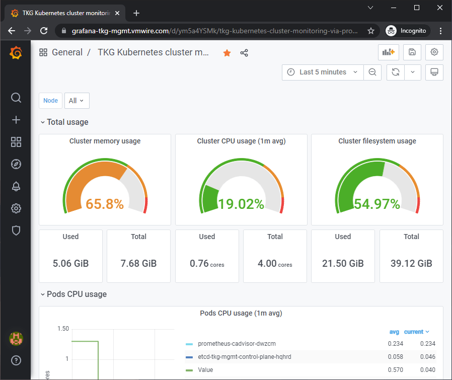
Since I’m using ingress to expose the Grafana service, also change line 33, from LoadBalancer to ClusterIP. This prevents Kapp from creating an unnecessary service that will consume an IP address.
Since I’m using ingress and I set the ingress FQDN as grafana-tkg-mgmt.vmwire.com and I also used TLS. I can now access the Grafana UI using https://grafana-tkg-mgmt.vmwire.com and enjoy a secure connection.
Listing all installed packages
tanzu package installed list -A
Making changes to Contour, Prometheus or Grafana
If you need to make changes to any of the configuration files, you can then update the deployment with the tanzu package installed update command.
This post shows how to run a replicated stateful application on local storage using a StatefulSet controller. This application is a replicated MySQL database. The example topology has a single primary server and multiple replicas, using asynchronous row-based replication. The MySQL data is using a storage class backed by local SSD storage provided by the vSphere CSI driver performing the dynamic PersistentVolume provisioner.
This post continues from the previous post where I described how to setup multi-AZ topology aware volume provisioning with local storage.
I used this example here to setup a StatefulSet with MySQL to get an example application up and running.
However, I did not use the default storage class, but added one line to the mysql-statefulset.yaml file to use the storage class that is backed by local SSDs instead.
I also appended the StatefulSet to include the spec.template.spec.affinity and spec.template.spec.podAntiAffinity settings to make use of the three AZs for pod scheduling.
spec:
  selector:
    matchLabels:
      app: mysql
  serviceName: mysql
  replicas: 3
  template:
    metadata:
      labels:
        app: mysql
    spec:
      affinity:
        nodeAffinity:
          requiredDuringSchedulingIgnoredDuringExecution:
            nodeSelectorTerms:
            - matchExpressions:
              - key: topology.csi.vmware.com/k8s-zone
                operator: In
                values:
                - az-1
                - az-2
                - az-3
        podAntiAffinity:
          requiredDuringSchedulingIgnoredDuringExecution:
          - labelSelector:
              matchExpressions:
              - key: app
                operator: In
                values:
                - mysql
            topologyKey: topology.csi.vmware.com/k8s-zone
Everything else stayed the same. Please spend some time reading the example from kubernetes.io as I will be performing the same steps but using local storage instead to test the behavior of MySQL replication.
Architecture
I am using the same setup, with three replicas in the StatefulSet to match with the three AZs that I have setup in my lab.
My AZ layout is the following.
AZ
ESX host
TKG worker
az-1
esx1.vcd.lab
tkg-hugo-md-0-7d455b7488-g28bl
az-2
esx2.vcd.lab
tkg-hugo-md-1-7bbd55cdb8-996×2
az-3
esx3.vcd.lab
tkg-hugo-md-2-6c6c49dc67-xbpg7
We can see which pod runs on which worker using the following command:
k get po -o wide
NAME                READY   STATUS    RESTARTS   AGE     IP               NODE                             NOMINATED NODE   READINESS GATES
mysql-0             2/2     Running   0          3h24m   100.120.135.67   tkg-hugo-md-1-7bbd55cdb8-996x2   <none>           <none>
mysql-1             2/2     Running   0          3h22m   100.127.29.3     tkg-hugo-md-0-7d455b7488-g28bl   <none>           <none>
mysql-2             2/2     Running   0          113m    100.109.206.65   tkg-hugo-md-2-6c6c49dc67-xbpg7   <none>           <none>
To see which PVCs are using which AZs using the CSI driver’s node affinity we can use this command.
kubectl get pv -o=jsonpath='{range .items[*]}{.metadata.name}{"\t"}{.spec.claimRef.name}{"\t"}{.spec.nodeAffinity}{"\n"}{end}'
The server_id’s are either 100, 101, or 102, referencing either mysql-0, mysql-1 or mysql-2 respectively. We can see that we can read data from all three of the pods which means our MySQL service is running well across all three AZs.
Simulating Pod and Node downtime
To demonstrate the increased availability of reading from the pool of replicas instead of a single server, keep the SELECT @@server_id loop from above running while you force a Pod out of the Ready state.
Delete Pods
The StatefulSet also recreates Pods if they’re deleted, similar to what a ReplicaSet does for stateless Pods.
kubectl delete pod mysql-2
The StatefulSet controller notices that no mysql-2 Pod exists anymore, and creates a new one with the same name and linked to the same PersistentVolumeClaim. You should see server ID 102 disappear from the loop output for a while and then return on its own.
Drain a Node
If your Kubernetes cluster has multiple Nodes, you can simulate Node downtime (such as when Nodes are upgraded) by issuing a drain.
We already know that mysql-2 is running on worker tkg-hugo-md-2. Then drain the Node by running the following command, which cordons it so no new Pods may schedule there, and then evicts any existing Pods.
What happens now is the pod mysql-2 will be evicted, it will also have its PVC unattached. Because we only have one worker per AZ, mysql-2 won’t be able to be scheduled on another node in another AZ.
The mysql-client-loop pod would show that 102 (mysql-2) is no longer serving MySQL requests. The pod mysql-2 will stay with a status as pending until a worker is available in AZ2 again.
Perform maintenance on ESX
After draining the worker node, we can now go ahead and perform maintenance operations on the ESX host by placing it into maintenance mode. Doing so will VMotion any VMs that are not using shared storage. You will find that because the worker node is still powered on and has locally attached VMDKs, this will prevent the ESX host from going into maintenance mode.
We know that the worker node is already drained and the MySQL application has two other replicas that are running in two other AZs, so we can safely power off this worker and enable the ESX host to complete going into maintenance mode. Yes, power off instead of gracefully shutting down. Kubernetes worker nodes are cattle and not pets and Kubernetes will destroy it anyway.
Operations with local storage
Consider the following when using local storage with Tanzu Kubernetes Grid.
TKG worker nodes that have been tagged with a k8s-zone and have attached PVs will not be able to VMotion.
TKG worker nodes that have been tagged with a k8s-zone and do not have attached PVs will also not be able to VMotion as they have the affinity rule set to “Must run on this host”.
Placing a ESX host into maintenance mode will not complete until the TKG worker node running on that host has been powered off.
However, do not be alarmed by any of this, as this is normal behavior. Kubernetes workers can be replaced very often and since we have a stateful application with more than one replica, we can do this with no consequences.
The following section shows why this is the case.
How do TKG clusters with local storage handle ESX maintenance?
To perform maintenance on an ESX host that requires a host reboot perform the following.
Drain the TKG worker node of the host that you want to place into maintenance mode
What this does is it evicts all pods but daemonsets, it will also evict the MySQL pod running on this node, including removing the volume mount. In our example here, we still have the other two MySQL pods running on two other worker nodes.
Now place the ESX host into maintenance mode.
Power off the TKG worker node on this ESX host to allow the host to go into maintenance mode.
You might notice that TKG will try to delete that worker node and clone a new worker node on this host, but it cannot due to the host being in maintenance mode. This is normal behavior as any Kubernetes clusters will try to replace a worker that is no longer accessible. This of course is the case as we have powered ours off.
You will notice that Kubernetes does not try to create a worker node on any other ESX host. This is because the powered-off worker is labelled with one of the AZs therefore Kubernetes tries to place a new worker in the same AZ.
Perform ESX maintenance as normal and when complete exit the host from maintenance mode.
When the host exits maintenance mode, you’ll notice that Kubernetes can now delete the powered-off worker and replace it with a new one.
When the new worker node powers on and becomes ready, you will notice that the previous PV that was attached to the now deleted worker node is now attached to the new worker node.
The MySQL pod will then claim the PV and the pod will start and come out of pending status into ready status.
All three MySQL pods are now up and running and we have a healthy MySQL cluster again. Any MySQL data that was changed during this maintenance window will be replicated to the MySQL pod.
Summary
Using local storage backed storage classes with TKG is a viable alternative to using shared storage when your applications can perform data protection and replication at a higher level. Applications such as databases like the MySQL example that I used can benefit from using cheaper locally attached fast solid state media such as SSD or NVMe without the need to create hyperconverged storage environments. Applications that can replicated data at the application level, can avoid using SAN and NAS completely and benefit from simpler infrastructures and lower costs as well as benefiting from faster storage and lower latencies.
With the vSphere CSI driver, it is now possible to use local storage with TKG clusters. This is enabled by TKG’s Topology Aware Volume Provisioning capability.
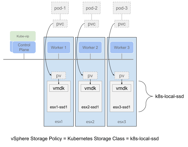
With this model, it is possible to present individual SSDs or NVMe drives attached to an ESXi host and configure a local datastore for use with topology aware volume provisioning. Kubernetes can then create persistent volumes and schedule pods that are deployed onto the worker nodes that are on the same ESXi host as the volume. This enables Kubernetes pods to have direct local access to the underlying storage.
With the vSphere CSI driver version 2.4.1, it is now possible to use local storage with TKG clusters. This is enabled by TKG’s Topology Aware Volume Provisioning capability.
Using local storage has distinct advantages over shared storage, especially when it comes to supporting faster and cheaper storage media for applications that do not benefit from or require the added complexity of having their data replicated by the storage layer. Examples of applications that do not require storage protection (RAID or failures to tolerate) are applications that can achieve data protection at the application level.
With this model, it is possible to present individual SSDs or NVMe drives attached to an ESXi host and configure a local datastore for use with topology aware volume provisioning. Kubernetes can then create persistent volumes and schedule pods that are deployed onto the worker nodes that are on the same ESXi host as the volume. This enables Kubernetes pods to have direct local access to the underlying storage.
Figure 1.
To setup such an environment, it is necessary to go over some of the requirements first.
Deploy Tanzu Kubernetes Clusters to Multiple Availability Zones on vSphere – link
Spread Nodes Across Multiple Hosts in a Single Compute Cluster
Configure Tanzu Kubernetes Plans and Clusters with an overlay that is topology-aware – link
Deploy TKG clusters into a multi-AZ topology
Deploy the k8s-local-ssd storage class
Deploy Workloads with WaitForFirstConsumer Mode in Topology-Aware Environment – link
Before you start
Note that only the CSI driver for vSphere version 2.4.1 supports local storage topology in a multi-AZ topology. To check if you have the correct version in your TKG cluster, run the following.
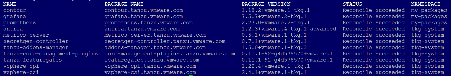
tanzu package installed get vsphere-csi -n tkg-system
- Retrieving installation details for vsphere-csi... I0224 19:20:29.397702  317993 request.go:665] Waited for 1.03368201s due to client-side throttling, not priority and fairness, request: GET:https://172.16.3.94:6443/apis/secretgen.k14s.io/v1alpha1?timeout=32s
\ Retrieving installation details for vsphere-csi...
NAME:                    vsphere-csi
PACKAGE-NAME:            vsphere-csi.tanzu.vmware.com
PACKAGE-VERSION:         2.4.1+vmware.1-tkg.1
STATUS:                  Reconcile succeeded
CONDITIONS:              [{ReconcileSucceeded True  }]
Deploy Tanzu Kubernetes Clusters to Multiple Availibility Zones on vSphere
In my example, I am using the Spread Nodes Across Multiple Hosts in a Single Compute Cluster example, each ESXi host is an availability zone (AZ) and the vSphere cluster is the Region.
Figure 1. shows a TKG cluster with three worker nodes, each node is running on a separate ESXi host. Each ESXi host has a local SSD drive formatted with VMFS 6. The topology aware volume provisioner would always place pods and their replicas on separate worker nodes and also any persistent volume claims (PVC) on separate ESXi hosts.
*Note that “cluster” is the name of my vSphere cluster.
Ensure that you’ve set up the correct rules that enforce worker nodes to their respective ESXi hosts. Always use “Must run on hosts in group“, this is very important for local storage topology to work. This is because the worker nodes will be labelled for topology awareness, and if a worker node is vMotion’d accidentally then the CSI driver will not be able to bind the PVC to the worker node.
Below is my vsphere-zones.yaml file.
Note that autoConfigure is set to true. Which means that you do not have to tag the cluster or the ESX hosts yourself, you would only need to setup up the affinity rules under Cluster, Configure, VM/Host Groups and VM/Host Rules. The setting autoConfigure: true, would then make CAPV automatically configure the tags and tag categories for you.
Note that Kubernetes does not like using parameter names that are not standard, I suggest for your vmGroupName and hostGroupName parameters, use lowercase and dashes instead of periods. For example host-group-3, instead of Host.Group.3. The latter will be rejected.
Configure Tanzu Kubernetes Plans and Clusters with an overlay that is topology-aware
To ensure that this topology can be built by TKG, we first need to create a TKG cluster plan overlay that tells Tanzu how what to do when creating worker nodes in a multi-availability zone topology.
Lets take a look at my az-overlay.yaml file.
Since I have three AZs, I need to create an overlay file that includes the cluster plan for all three AZs.
To deploy a TKG cluster that spreads its worker nodes over multiple AZs, we need to add some key value pairs into the cluster config file.
Below is an example for my cluster config file – tkg-hugo.yaml.
The new key value pairs are described in the table below.
Parameter
Specification
Details
VSPHERE_REGION
k8s-region
Must be the same as the configuration in the vsphere-zones.yaml file
VSPHERE_ZONE
k8s-zone
Must be the same as the configuration in the vsphere-zones.yaml file
VSPHERE_AZ_0 VSPHERE_AZ_1 VSPHERE_AZ_2
az-1 az-2 az-3
Must be the same as the configuration in the vsphere-zones.yaml file
WORKER_MACHINE_COUNT
3
This is the number of worker nodes for the cluster.
The total number of workers are distributed in a round-robin fashion across the number of AZs specified.
A note on WORKER_MACHINE_COUNT when using CLUSTER_PLAN: dev instead of prod.
If you change the az-overlay.yaml @ if data.values.CLUSTER_PLAN == “prod” to @ if data.values.CLUSTER_PLAN == “dev”
Then the WORKER_MACHINE_COUNT reverts to the number of workers for each AZ. So if you set this number to 3, in a three AZ topology, you would end up with a TKG cluster with nine workers!
Note that parameters.storagePolicyName: k8s-local-ssd, which is the same as the name of the storage policy for the local storage. All three of the local VMFS datastores that are backed by the local SSD drives are members of this storage policy.
Note that the volumeBindingMode is set to WaitForFirstConsumer.
Instead of creating a volume immediately, the WaitForFirstConsumer setting instructs the volume provisioner to wait until a pod using the associated PVC runs through scheduling. In contrast with the Immediate volume binding mode, when the WaitForFirstConsumer setting is used, the Kubernetes scheduler drives the decision of which failure domain to use for volume provisioning using the pod policies.
This guarantees the pod at its volume is always on the same AZ (ESXi host).
Deploy a workload that uses Topology Aware Volume Provisioning
Below is a statefulset that deploys three pods running nginx. It configures two persistent volumes, one for www and another for log. Both of these volumes are going to be provisioned onto the same ESXi host where the pod is running. The statefulset also runs an initContainer that will download a simple html file from my repo and copy it to the www mount point (/user/share/nginx/html).
You can see under spec.affinity.nodeAffinity how the statefulset uses the topology.
The statefulset then exposes the nginx app using the nginx-service which uses the Gateway API, that I wrote about in a previous blog post.
What if you wanted to use more than three availability zones?
Some notes here on what I experienced during my testing.
The TKG cluster config has the following three lines to specify the names of the AZs that you want to use which will be passed onto the Tanzu CLI to use to deploy your TKG cluster using the ytt overlay file. However, the Tanzu CLI only supports a total of three AZs.
If you wanted to use more than three AZs, then you would have to remove these three lines from the TKG cluster config and change the ytt overlay to not use the VSPHERE_AZ_# variables but to hard code the AZs into the ytt overlay file instead.
To do this replace the following:
      #@ if data.values.VSPHERE_AZ_2:
      failureDomain: #@ data.values.VSPHERE_AZ_0
      #@ end
with the following:
failureDomain: az-2
and create an additional block of MachineDeployment and KubeadmConfigTemplate for each additional AZ that you need.
Summary
Below are screenshots and the resulting deployed objects after running kubectl apply -f to the above.
kubectl get nodes
NAME                             STATUS   ROLES                  AGE     VERSION
tkg-hugo-md-0-7d455b7488-d6jrl   Ready    <none>                 3h23m   v1.22.5+vmware.1
tkg-hugo-md-1-bc76659f7-cntn4    Ready    <none>                 3h23m   v1.22.5+vmware.1
tkg-hugo-md-2-6bb75968c4-mnrk5   Ready    <none>                 3h23m   v1.22.5+vmware.1
You can see that the worker nodes are distributed across the ESXi hosts as per our vsphere-zones.yaml and also our az-overlay.yaml files.
kubectl get po -o wide
NAME    READY   STATUS    RESTARTS   AGE     IP                NODE                             NOMINATED NODE   READINESS GATES
web-0   1/1     Running   0          3h14m   100.124.232.195   tkg-hugo-md-2-6bb75968c4-mnrk5   <none>           <none>
web-1   1/1     Running   0          3h13m   100.122.148.67    tkg-hugo-md-1-bc76659f7-cntn4    <none>           <none>
web-2   1/1     Running   0          3h12m   100.108.145.68    tkg-hugo-md-0-7d455b7488-d6jrl   <none>           <none>
You can see that each pod is placed on a separate worker node.
kubectl get csinodes -o jsonpath='{range .items[*]}{.metadata.name} {.spec}{"\n"}{end}'
In a previous post I went through how to deploy the Kubernetes Dashboard into a Kubernetes cluster with default settings, running with a self-signed certificate. This post covers how to update the configuration to use a signed certificate. I’m a fan of Let’s Encrypt so will be using a signed wildcard certificate from Let’s Encrypt for this post.
In a previous post I went through how to deploy the Kubernetes Dashboard into a Kubernetes cluster with default settings, running with a self-signed certificate. This post covers how to update the configuration to use a signed certificate. I’m a fan of Let’s Encrypt so will be using a signed wildcard certificate from Let’s Encrypt for this post.
You can prepare Let’s Encrypt by referring to a previous post here.
Step 1. Create a new namespace
Create a new namespace for Kubernetes Dashboard
kubectl create ns kubernetes-dashboard
Step 2. Upload certificates
Upload your certificate and private key to $HOME/certs in pem format. Let’s Encrypt just happens to issue certificates in pem format with the following names:
cert.pem and privkey.pem
All we need to do is to rename these to:
tls.crt and tls.key
And then upload them to $HOME/certs where our kubectl tool is installed.
Step 3. Create secret
Create the secret for the custom certificate by running this command.
Save changes to the file. Now we’re ready to deploy.
If you want to use the Avi Services API (K8s Gateway API). Then add labels to the service, like this. This will ensure that the service uses the Avi gateway.
This post describes how to setup Harbor to run on a standalone VM. There are times when you want to do this, such as occasions where your environment does not have internet access or you want to have a local repository running close to your environment.
This post describes how to setup Harbor to run on a standalone VM. There are times when you want to do this, such as occasions where your environment does not have internet access or you want to have a local repository running close to your environment.
I found that I was running a lot of TKG deployments against TKG staging builds in my lab and wanted to speed up cluster creation times, so building a local Harbor repository would make things a bit quicker and more reliable.
This post describes how you can setup a Harbor repository on a Photon VM.
# Configuration file of Harbor

# The IP address or hostname to access admin UI and registry service.
# DO NOT use localhost or 127.0.0.1, because Harbor needs to be accessed by external clients.
hostname: harbor.vmwire.com

# http related config
http:
  # port for http, default is 80. If https enabled, this port will redirect to https port
  port: 80

# https related config
https:
  # https port for harbor, default is 443
  port: 443
  # The path of cert and key files for nginx
  certificate: /etc/docker/certs.d/harbor.vmwire.com/harbor.cert
  private_key: /etc/docker/certs.d/harbor.vmwire.com/harbor_key.key

[snipped]
Update line 5 with your harbor instance’s FQDN.
Update lines 17 and 18 with the certificate and private key.
You can leave all the other lines on default.
Install Harbor with the following command:
./install.sh
Check to see if services are running
docker-compose ps
Step 9: Add harbor FQDN to your DNS servers and connect to Harbor.
To upgrade, download the new offline installer and run
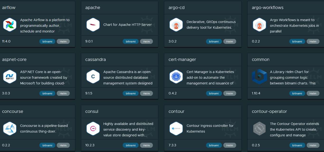
Kubeapps is a web-based UI for deploying and managing applications in Kubernetes clusters. This guide shows how you can deploy Kubeapps into your TKG clusters deployed in VMware Cloud Director.
Kubeapps is a web-based UI for deploying and managing applications in Kubernetes clusters. This guide shows how you can deploy Kubeapps into your TKG clusters deployed in VMware Cloud Director.
With Kubeapps you can:
Customize deployments through an intuitive, form-based user interface
Inspect, upgrade and delete applications installed in the cluster
Avi (NSX Advanced Load Balancer) supports Kubernetes Gateway API. This post shows how to install and use the Gateway API to expose applications using this custom resource definition (CRD).
Introduction
Avi (NSX Advanced Load Balancer) supports Kubernetes Gateway API. This post shows how to install and use the Gateway API to expose applications using this custom resource definition (CRD).
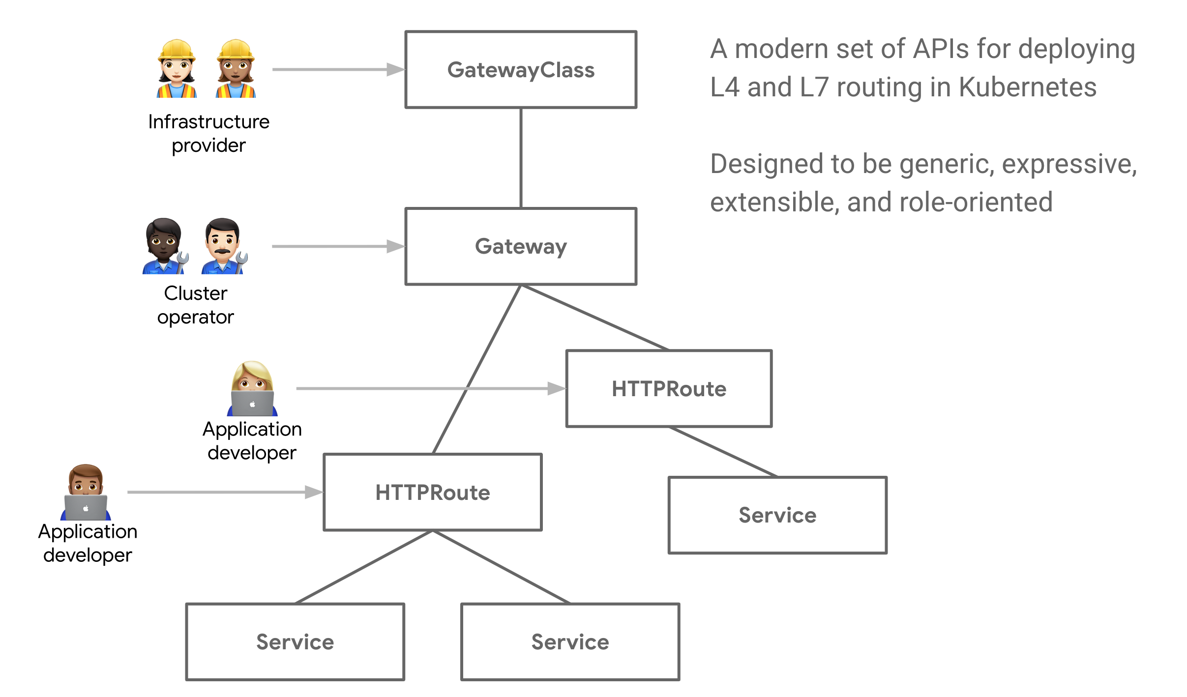
Gateway API is an open source project managed by the SIG-NETWORK community. It is a collection of resources that model service networking in Kubernetes. These resources – GatewayClass,Gateway, HTTPRoute, TCPRoute, Service, etc – aim to evolve Kubernetes service networking through expressive, extensible, and role-oriented interfaces that are implemented by many vendors and have broad industry support.
For a quick introduction to the Kubernetes Gateway API, read this link and this link from the Avi documentation.
Why use Gateway API?
You would want to use the Gateway API if you had the following requirements:
Network segmentation – exposing applications from the same Kubernetes cluster to different network segments
Shared IP – exposing multiple services that use both TCP and UDP ports on the same IP address
NSX Advanced Load Balancer supports both of these requirements through the use of the Gateway API. The following section describes how this is implemented.
The Gateway API introduces a few new resource types:
GatewayClasses are cluster-scoped resources that act as templates to explicitly define behavior for Gateways derived from them. This is similar in concept to StorageClasses, but for networking data-planes.
Gateways are the deployed instances of GatewayClasses. They are the logical representation of the data-plane which performs routing, which may be in-cluster proxies, hardware LBs, or cloud LBs.
AVI Infra Setting
Aviinfrasetting provides a way to segregate Layer-4/Layer-7 virtual services to have properties based on different underlying infrastructure components, like Service Engine Group, intended VIP Network etc.
Avi Infra Setting is a cluster scoped CRD and can be attached to the intended Services. Avi Infra setting resources can be attached to Services using Gateway APIs.
GatewayClass
Gateway APIs provide interfaces to structure Kubernetes service networking.
AKO supports Gateway APIs via the servicesAPI flag in the values.yaml.
The Avi Infra Setting resource can be attached to a Gateway Class object, via the .spec.parametersRef as shown below:
The Gateway object provides a way to configure multiple Services as backends to the Gateway using label matching. The labels are specified as constant key-value pairs, the keys being ako.vmware.com/gateway-namespace and ako.vmware.com/gateway-name. The values corresponding to these keys must match the Gateway namespace and name respectively, for AKO to consider the Gateway valid. In case any one of the label keys are not provided as part of matchLabels OR the namespace/name provided in the label values do no match the actual Gateway namespace/name, AKO will consider the Gateway invalid.
A Gateway uses a GatewayClass, which in turn uses an AviInfraSetting. Therefore when a Gateway is used by a Service using the relevant labels, that particular service will be exposed on a network that is referenced by the AviInfraSetting via the .spec.network.vipNetworks
In your helm charts, for any service that needs a LoadBalancer service. You would now want to use ClusterIP instead of LoadBalancer and use Labels such as the following:
and the ClusterIP type tells the AKO operator to use the gateways, each gateway is on a separate network segment for traffic separation via the spec.gatewayClassName and conversely the gatewayclass via the spec.parametersRef.name for the AviInfraSetting.
This post describes how to change TKGm control plane nodes resources, such as vCPU and RAM. In the previous post, I described how to increase resources for a worker node. This process was quite simple and straightforward and initially I had a tough time finding the right resource to edit as the control plane nodes use a different resource to provision the virtual machines.
This post describes how to change TKGm control plane nodes resources, such as vCPU and RAM. In the previous post, I described how to increase resources for a worker node. This process was quite simple and straightforward and initially I had a tough time finding the right resource to edit as the control plane nodes use a different resource to provision the virtual machines.
Step 1. Change to the TKG management cluster context
kubectl config use-context tkg-mgmt
Step 2. List VSphereMachineTemplate
kubectl get VSphereMachineTemplate
Step 4. Make a copy of the current control plane VsphereMachineTemplate to a new file
kubectl get vspheremachinetemplates tkg-ssc-control-plane -o yaml > tkg-ssc-control-plane-new.yaml
Change line 32, to use the new VsphereMachineTemplate called tkg-ssc-control-plane-new. Once you save and quit with :wq! the control plane nodes will be re-deployed.
Envoy is configured to run as a non-root user by default. This is much more secure but we won’t be able to use any ports that are lower than 1024. Therefore we must change the values.yaml file for contour.
Edit the values.yaml file located in the directory that you untar the tkz file into and search for
envoy.containerPorts.http
Change the http port to 8080 and the https port to 8443.
It should end up looking like this:
  containerPorts:
    http: 8080
    https: 8443
Step 4. Installing Contour (and Envoy)
Install Contour by running the following command
helm install ingress <path-to-contour-directory>
You should get one daemonset named ingress-contour-envoy and deployment named ingress-contour-contour. These spin up two pods.
You will also see two services starting, one called ingress-contour with a service type of ClusterIP and another called ingress-contour-envoy with a service type LoadBalancer. Wait for NSX ALB to assign an external IP for the envoy service from your Organization network IP pool.
This IP is now your Kubernetes cluster IP for ingress services. Make a note of this IP address. My example uses 10.149.1.116 as the external IP.
Step 5. Setup DNS
The next step to do is to setup DNS, I’m using Windows DNS in my lab so what I’ve done is setup a sub domain called apps.vmwire.com and also setup an A record pointing to *.apps.vmwire.com.
*.apps.vmwire.com 10.149.1.116
DNS is now setup to point *.apps.vmwire.com to the external IP assigned to Envoy. From this point forward, any DNS request that hits *.apps.vmwire.com will be redirected to Contour.
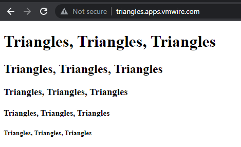
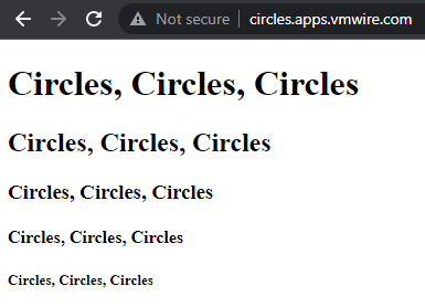
They are two yaml files that deploys a sample web application and then exposes the applications using Contour and Envoy.
You don’t have to edit the shapes.yaml file, but you will need to edit the shapes-ingress.yaml file and change lines 9 and 16 to your desired DNS settings.
In this example, Contour will use circles.apps.vmwire.com to expose the circles application and triangles.apps.vmwire.com to expose the triangles application. Note that we are not adding circles. or triangles. A records into the DNS server.
Lets deploy the circles and triangles apps.
kubectl apply -f shapes.yaml
And then expose the applications with Contour
kubectl apply -f shapes-ingress.yaml
Now open up a web browser and navigate to http://circles.<your-domain> or http://triangles.<your-domain> and see the apps being exposed by Contour. If you don’t get a connection, its probably because you haven’t enabled port 80 through your Edge Gateway.
will easily do this for you, this is known as horizontal scale-out. But have you thought of how to scale-up control plane or worker nodes with more CPU or memory?
This post discusses how you can scale up a TKGm worker node, tl;dr how to increase or decrease worker node CPU, RAM, disk.
Getting started
It is not a simple process to scale-up as it is to scale-out. Follow the steps below to scale-up your TKGm cluster.
Step 1.
Run the following command to obtain the list of vSphere machine templates that TKGm uses to deploy control plane and worker nodes.
kubectl get vspheremachinetemplate
NAME                             AGE
tkg-ssc-control-plane            3d1h
tkg-ssc-worker                   3d1h
tkg-workload-01-control-plane    3d
tkg-workload-01-worker           3d
You can see that there are four machine templates.
Lets say we want to increase the size of the worker nodes in the tkg-workload-01 cluster.
Lets describe the tkg-workload-01-worker machine template.
You can see that this machine template has 16GB of RAM and 4 vCPUs. Lets say we want to increase workers to 120GB of RAM and 24 vCPUs, how would we do this?
Step 2.
We need to clone the currently in use machine template into a new one and then apply it.
kubectl get vspheremachinetemplate tkg-workload-01-worker -o yaml > new-machine-template.yaml
Step 3.
Now that we have exported the current machine template into a new yaml file, we can edit it to suit our needs. Edi the file and make the changes to the file.
Change lines 6 and 9 by appending a new name to the machine template, you’ll notice that the original name was tkg-workload-01-worker, I appended “scale” to it so the new name of this new machine template is tkg-workload-01-worker-scale.
Step 4.
We can now apply the new machine template with this command
kubectl apply –f new-machine-template.yaml
We can check that the new machine template exists by running this command
kubectl get vspheremachinetemplate
NAME                             AGE
tkg-ssc-control-plane            3d1h
tkg-ssc-worker                   3d1h
tkg-workload-01-control-plane    3d
tkg-workload-01-worker           3d
tkg-workload-01-worker-scale     10s
Step 5.
Now we can apply the new machine template to our cluster.
Before doing that, we need to obtain the machine deployment details for the tkg-workload-01 cluster, we can get this information by running these commands
The line that we are interested in is line 38. This is the current machine template that this cluster is using, you’ll notice that it is of course using the original spec, what we need to do is change it to the new spec that we created earlier. If you remember, we named that one tkg-workload-01-worker-scale.
# Please edit the object below. Lines beginning with a '#' will be ignored,
# and an empty file will abort the edit. If an error occurs while saving this file will be
# reopened with the relevant failures.
#
apiVersion: cluster.x-k8s.io/v1alpha3
kind: MachineDeployment
metadata:
  annotations:
    kubectl.kubernetes.io/last-applied-configuration: |
      {"apiVersion":"cluster.x-k8s.io/v1alpha3","kind":"MachineDeployment","metadata":{"annotations":{},"labels":{"cluster.x-k8s.io/cluster-name":"tkg-workload-01"},"name":"tkg-workload-01-md-0","namespace":"default"},"spec":{"clusterName":"tkg-workload-01","replicas":4,"selector":{"matchLabels":{"cluster.x-k8s.io/cluster-name":"tkg-workload-01"}},"template":{"metadata":{"labels":{"cluster.x-k8s.io/cluster-name":"tkg-workload-01","node-pool":"tkg-workload-01-worker-pool"}},"spec":{"bootstrap":{"configRef":{"apiVersion":"bootstrap.cluster.x-k8s.io/v1alpha3","kind":"KubeadmConfigTemplate","name":"tkg-workload-01-md-0"}},"clusterName":"tkg-workload-01","infrastructureRef":{"apiVersion":"infrastructure.cluster.x-k8s.io/v1alpha3","kind":"VSphereMachineTemplate","name":"tkg-workload-01-worker"},"version":"v1.21.2+vmware.1"}}}}
    machinedeployment.clusters.x-k8s.io/revision: "3"
  creationTimestamp: "2021-10-29T14:11:25Z"
  generation: 7
  labels:
    cluster.x-k8s.io/cluster-name: tkg-workload-01
  name: tkg-workload-01-md-0
  namespace: default
  ownerReferences:
  - apiVersion: cluster.x-k8s.io/v1alpha3
    kind: Cluster
    name: tkg-workload-01
    uid: be507594-0c05-4d30-8ed6-56811733df23
  resourceVersion: "1665423"
  uid: 5148e564-cf66-4581-8941-c3024c58967e
spec:
  clusterName: tkg-workload-01
  minReadySeconds: 0
  progressDeadlineSeconds: 600
  replicas: 4
  revisionHistoryLimit: 1
  selector:
    matchLabels:
      cluster.x-k8s.io/cluster-name: tkg-workload-01
  strategy:
    rollingUpdate:
      maxSurge: 1
      maxUnavailable: 0
    type: RollingUpdate
  template:
    metadata:
      labels:
        cluster.x-k8s.io/cluster-name: tkg-workload-01
        node-pool: tkg-workload-01-worker-pool
    spec:
      bootstrap:
        configRef:
          apiVersion: bootstrap.cluster.x-k8s.io/v1alpha3
          kind: KubeadmConfigTemplate
          name: tkg-workload-01-md-0
      clusterName: tkg-workload-01
      infrastructureRef:
        apiVersion: infrastructure.cluster.x-k8s.io/v1alpha3
        kind: VSphereMachineTemplate
        name: tkg-workload-01-worker-scale
      version: v1.21.2+vmware.1
status:
  availableReplicas: 4
  observedGeneration: 7
  phase: Running
  readyReplicas: 4
  replicas: 4
  selector: cluster.x-k8s.io/cluster-name=tkg-workload-01
  updatedReplicas: 4
The line that we are interested in is line 54. We need to change the machine template from that old one to our new one.
Lets make that change by going down to line 54 and adding “-scale” to the end of that line. Once you save and quit using “:wq!”. Kubernetes will make do a rolling update of your TKGm cluster for you.
Finishing off
Once the rolling update is done, you can check vSphere Web Client for new VMs being cloned and old ones being deleted. You can also run the command below to see the status of the rolling updates.
kubectl get MachineDeployment
You’ll then see that your new worker nodes have been resized without interrupting any of the running pods in the cluster.
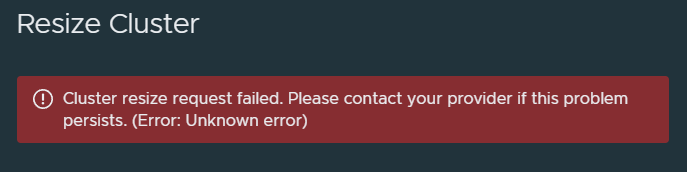
When trying to resize a TKGm cluster with CSE, you might encounter this error below:
Cluster resize request failed. Please contact your provider if this problem persists. (Error: Unknown error)
This post shows how you can use the vcd cse cli to workaround this problem.
When trying to resize a TKGm cluster with CSE in the VCD UI, you might encounter this error below:
Cluster resize request failed. Please contact your provider if this problem persists. (Error: Unknown error)
Checking the logs in ~/.cse-logs there are no logs that show what the error is. It appears to be an issue with the Container UI Plugin for CSE 3.1.0.
If you review the console messages in Chrome’s developer tools you might see something like the following:
TypeError: Cannot read properties of null (reading 'length')
    at getFullSpec (https://vcd.vmwire.com/tenant/tenant1/uiPlugins/80134fc9-86e1-41db-9d02-b02d5e9e1e3c/ca5642fa-7186-4da2-b273-2dbd3451fd50/bundle.js:1:170675)
    at resizeCseCluster
This post shows how you can use the vcd cse cli to workaround this problem.
Using the vcd cse cli to resize a TKGm cluster
First log into the CSE appliance or somewhere with vcd cse cli installed
Then log into the VCD Org that has the cluster that you want to resize with a user with the role with the cse:nativecluster rights bundle.
Change the workers: count to your new desired number of workers.
Save this file as update_my_cluster.yaml
Update the cluster with this command
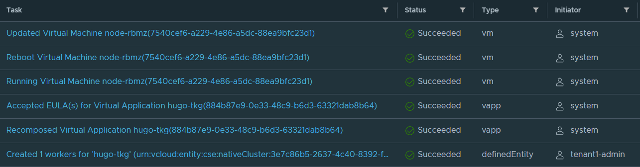
vcd cse cluster apply update_my_cluster.yaml
You’ll notice that CSE will deploy another worker node into the same vApp and after a few minutes your TKGm cluster will have another node added to it.
root@photon-manager [ ~/.kube ]# kubectl get nodes
NAME        STATUS   ROLES                  AGE   VERSION
mstr-zcn7   Ready    control-plane,master   14m   v1.20.5+vmware.2
node-7swy   Ready    <none>                 10m   v1.20.5+vmware.2
node-90sb   Ready    <none>                 12m   v1.20.5+vmware.2
root@photon-manager [ ~/.kube ]# kubectl get nodes
NAME        STATUS   ROLES                  AGE   VERSION
mstr-zcn7   Ready    control-plane,master   22m   v1.20.5+vmware.2
node-7swy   Ready    <none>                 17m   v1.20.5+vmware.2
node-90sb   Ready    <none>                 19m   v1.20.5+vmware.2
node-rbmz   Ready    <none>                 43s   v1.20.5+vmware.2
Viewing client logs
The vcd cse cli commands are client side, to enable logging for this do the following
Run this command in the CSE appliance or on your workstation that has the vcd cse cli installed.
CSE_CLIENT_WIRE_LOGGING=True
View the logs by using this command
tail -f cse-client-debug.log
A couple of notes
The vcd cse cluster resize command is not enabled if your CSE server is using legacy_mode: false. You can read up on this in this link.
Therefore, the only way to resize a cluster is to update it using the vcd cse cluster apply command. The apply command supports the following:
apply a configuration to a cluster resource by filename. The resource will be created if it does not exist. (The command can be used to create the cluster, scale-up/down worker count, scale-up NFS nodes, upgrade the cluster to a new K8s version.
CSE 3.1.1 can only scale-up a TKGm cluster, it does not support scale-down yet.
This post uses a statefulset to deploy nginx with pvc and load balancer services into a Kubernetes cluster running in VMware Cloud Director enabled with Container Service Extension.
VCD has a cloud provider named vmware-cloud-director-ccm-0 and a CSI provider named csi-vcd-controllerplugin-0.
This post uses a statefulset to deploy nginx with pvc and load balancer services into a Kubernetes cluster running in VMware Cloud Director enabled with Container Service Extension.
VCD has a cloud provider named vmware-cloud-director-ccm-0 and a CSI provider named csi-vcd-controllerplugin-0.
If you sent the following command to a Kubernetes cluster
Lets deploy into a new namespace, for that we create a new namespace first.
kubectl create ns web-statefulset
Deploy the statefulset with the following command
kubectl apply -f web-statefulset.yaml
You’ll see named disks and ingress services create in VCD and Avi respectively.
If you tried to access the nginx webpage using the service IP address, you wouldn’t see any web page, although the connection is working. This is because the nginx app using the /usr/share/nginx/html mount point to an empty PVC. We need to copy a basic index.html into that directory to get a webpage.
We can do that by logging into the pod and downloading a sample index.html for nginx.
Bash auto completion is very useful, it’ll save you time and avoids unnecessary typos. This quick guide shows you how to setup bash auto completion for Photon OS so that you can use kubectl commands and complete them using the [TAB] key on your keyboard.
Bash auto completion is very useful, it’ll save you time and avoids unnecessary typos. This quick guide shows you how to setup bash auto completion for Photon OS so that you can use kubectl commands and complete them using the [TAB] key on your keyboard. It also works to auto complete kubernetes resources too. For example you could type kubectl describe ns <first-couple-of letters-of-namespace> and press [TAB], bash auto completion will then complete the rest for you.
Additionally, we will install kubectx to enable fast context switching between contexts. To use kubectl, just type kubectl and press enter, you can then use your cursor to move between contexts.
The Linux package bash-completion should already be installed in Photon.
Photon OS 3 does not support Linux guest customization unfortunately, so we will use the links below to manually setup the OS with a hostname and static IP address.
Boot the VM, the default credentials are root with password changeme. Change the default password.
Photon 3 has the older repositories, so we will need to update to newer repositories as detailed in this KB article. I’ve included this in the instructions below.
Copypasta or use create a bash script.
# Update Photon repositories
cd /etc/yum.repos.d/
sed  -i 's/dl.bintray.com\/vmware/packages.vmware.com\/photon\/$releasever/g' photon.repo photon-updates.repo photon-extras.repo photon-debuginfo.repo

# If you get errors with the above command, then copy the command from the KB article.

# Update Photon
tdnf --assumeyes update

# Install dependencies
tdnf --assumeyes install build-essential python3-devel python3-pip git

# Update python3, cse supports python3 version 3.7.3 or greater, it does not support python 3.8 or above.
tdnf --assumeyes update python3

# Prepare cse user and application directories
mkdir -p /opt/vmware/cse
chmod 775 -R /opt
chmod 777 /
groupadd cse
useradd cse -g cse -m -p Vmware1! -d /opt/vmware/cse
chown cse:cse -R /opt

# Run as cse user, add your public ssh key to CSE server
su - cse
mkdir -p ~/.ssh
cat >> ~/.ssh/authorized_keys << EOF
ssh-rsa AAAAB3NzaC1yc2EAAAABJQAAAQEAhcw67bz3xRjyhPLysMhUHJPhmatJkmPUdMUEZre+MeiDhC602jkRUNVu43Nk8iD/I07kLxdAdVPZNoZuWE7WBjmn13xf0Ki2hSH/47z3ObXrd8Vleq0CXa+qRnCeYM3FiKb4D5IfL4XkHW83qwp8PuX8FHJrXY8RacVaOWXrESCnl3cSC0tA3eVxWoJ1kwHxhSTfJ9xBtKyCqkoulqyqFYU2A1oMazaK9TYWKmtcYRn27CC1Jrwawt2zfbNsQbHx1jlDoIO6FLz8Dfkm0DToanw0GoHs2Q+uXJ8ve/oBs0VJZFYPquBmcyfny4WIh4L0lwzsiAVWJ6PvzF5HMuNcwQ== rsa-key-20210508
EOF

cat >> ~/.bash_profile << EOF
# For Container Service Extension
export CSE_CONFIG=/opt/vmware/cse/config/config.yaml
export CSE_CONFIG_PASSWORD=Vmware1!
source /opt/vmware/cse/python/bin/activate
EOF

# Install CSE in virtual environment
python3 -m venv /opt/vmware/cse/python
source /opt/vmware/cse/python/bin/activate
pip3 install container-service-extension==3.1.1

cse version

source ~/.bash_profile

# Prepare vcd-cli
mkdir -p ~/.vcd-cli
cat >  ~/.vcd-cli/profiles.yaml << EOF
extensions:
- container_service_extension.client.cse
EOF

vcd cse version

# Add my Let's Encrypt intermediate and root certs. Use your certificates issued by your CA to enable verify=true with CSE.
cat >> /opt/vmware/cse/python/lib/python3.7/site-packages/certifi/cacert.pem << EOF
-----BEGIN CERTIFICATE-----
MIIFFjCCAv6gAwIBAgIRAJErCErPDBinU/bWLiWnX1owDQYJKoZIhvcNAQELBQAw
TzELMAkGA1UEBhMCVVMxKTAnBgNVBAoTIEludGVybmV0IFNlY3VyaXR5IFJlc2Vh
cmNoIEdyb3VwMRUwEwYDVQQDEwxJU1JHIFJvb3QgWDEwHhcNMjAwOTA0MDAwMDAw
WhcNMjUwOTE1MTYwMDAwWjAyMQswCQYDVQQGEwJVUzEWMBQGA1UEChMNTGV0J3Mg
RW5jcnlwdDELMAkGA1UEAxMCUjMwggEiMA0GCSqGSIb3DQEBAQUAA4IBDwAwggEK
AoIBAQC7AhUozPaglNMPEuyNVZLD+ILxmaZ6QoinXSaqtSu5xUyxr45r+XXIo9cP
R5QUVTVXjJ6oojkZ9YI8QqlObvU7wy7bjcCwXPNZOOftz2nwWgsbvsCUJCWH+jdx
sxPnHKzhm+/b5DtFUkWWqcFTzjTIUu61ru2P3mBw4qVUq7ZtDpelQDRrK9O8Zutm
NHz6a4uPVymZ+DAXXbpyb/uBxa3Shlg9F8fnCbvxK/eG3MHacV3URuPMrSXBiLxg
Z3Vms/EY96Jc5lP/Ooi2R6X/ExjqmAl3P51T+c8B5fWmcBcUr2Ok/5mzk53cU6cG
/kiFHaFpriV1uxPMUgP17VGhi9sVAgMBAAGjggEIMIIBBDAOBgNVHQ8BAf8EBAMC
AYYwHQYDVR0lBBYwFAYIKwYBBQUHAwIGCCsGAQUFBwMBMBIGA1UdEwEB/wQIMAYB
Af8CAQAwHQYDVR0OBBYEFBQusxe3WFbLrlAJQOYfr52LFMLGMB8GA1UdIwQYMBaA
FHm0WeZ7tuXkAXOACIjIGlj26ZtuMDIGCCsGAQUFBwEBBCYwJDAiBggrBgEFBQcw
AoYWaHR0cDovL3gxLmkubGVuY3Iub3JnLzAnBgNVHR8EIDAeMBygGqAYhhZodHRw
Oi8veDEuYy5sZW5jci5vcmcvMCIGA1UdIAQbMBkwCAYGZ4EMAQIBMA0GCysGAQQB
gt8TAQEBMA0GCSqGSIb3DQEBCwUAA4ICAQCFyk5HPqP3hUSFvNVneLKYY611TR6W
PTNlclQtgaDqw+34IL9fzLdwALduO/ZelN7kIJ+m74uyA+eitRY8kc607TkC53wl
ikfmZW4/RvTZ8M6UK+5UzhK8jCdLuMGYL6KvzXGRSgi3yLgjewQtCPkIVz6D2QQz
CkcheAmCJ8MqyJu5zlzyZMjAvnnAT45tRAxekrsu94sQ4egdRCnbWSDtY7kh+BIm
lJNXoB1lBMEKIq4QDUOXoRgffuDghje1WrG9ML+Hbisq/yFOGwXD9RiX8F6sw6W4
avAuvDszue5L3sz85K+EC4Y/wFVDNvZo4TYXao6Z0f+lQKc0t8DQYzk1OXVu8rp2
yJMC6alLbBfODALZvYH7n7do1AZls4I9d1P4jnkDrQoxB3UqQ9hVl3LEKQ73xF1O
yK5GhDDX8oVfGKF5u+decIsH4YaTw7mP3GFxJSqv3+0lUFJoi5Lc5da149p90Ids
hCExroL1+7mryIkXPeFM5TgO9r0rvZaBFOvV2z0gp35Z0+L4WPlbuEjN/lxPFin+
HlUjr8gRsI3qfJOQFy/9rKIJR0Y/8Omwt/8oTWgy1mdeHmmjk7j1nYsvC9JSQ6Zv
MldlTTKB3zhThV1+XWYp6rjd5JW1zbVWEkLNxE7GJThEUG3szgBVGP7pSWTUTsqX
nLRbwHOoq7hHwg==
-----END CERTIFICATE-----
-----BEGIN CERTIFICATE-----
MIIFazCCA1OgAwIBAgIRAIIQz7DSQONZRGPgu2OCiwAwDQYJKoZIhvcNAQELBQAw
TzELMAkGA1UEBhMCVVMxKTAnBgNVBAoTIEludGVybmV0IFNlY3VyaXR5IFJlc2Vh
cmNoIEdyb3VwMRUwEwYDVQQDEwxJU1JHIFJvb3QgWDEwHhcNMTUwNjA0MTEwNDM4
WhcNMzUwNjA0MTEwNDM4WjBPMQswCQYDVQQGEwJVUzEpMCcGA1UEChMgSW50ZXJu
ZXQgU2VjdXJpdHkgUmVzZWFyY2ggR3JvdXAxFTATBgNVBAMTDElTUkcgUm9vdCBY
MTCCAiIwDQYJKoZIhvcNAQEBBQADggIPADCCAgoCggIBAK3oJHP0FDfzm54rVygc
h77ct984kIxuPOZXoHj3dcKi/vVqbvYATyjb3miGbESTtrFj/RQSa78f0uoxmyF+
0TM8ukj13Xnfs7j/EvEhmkvBioZxaUpmZmyPfjxwv60pIgbz5MDmgK7iS4+3mX6U
A5/TR5d8mUgjU+g4rk8Kb4Mu0UlXjIB0ttov0DiNewNwIRt18jA8+o+u3dpjq+sW
T8KOEUt+zwvo/7V3LvSye0rgTBIlDHCNAymg4VMk7BPZ7hm/ELNKjD+Jo2FR3qyH
B5T0Y3HsLuJvW5iB4YlcNHlsdu87kGJ55tukmi8mxdAQ4Q7e2RCOFvu396j3x+UC
B5iPNgiV5+I3lg02dZ77DnKxHZu8A/lJBdiB3QW0KtZB6awBdpUKD9jf1b0SHzUv
KBds0pjBqAlkd25HN7rOrFleaJ1/ctaJxQZBKT5ZPt0m9STJEadao0xAH0ahmbWn
OlFuhjuefXKnEgV4We0+UXgVCwOPjdAvBbI+e0ocS3MFEvzG6uBQE3xDk3SzynTn
jh8BCNAw1FtxNrQHusEwMFxIt4I7mKZ9YIqioymCzLq9gwQbooMDQaHWBfEbwrbw
qHyGO0aoSCqI3Haadr8faqU9GY/rOPNk3sgrDQoo//fb4hVC1CLQJ13hef4Y53CI
rU7m2Ys6xt0nUW7/vGT1M0NPAgMBAAGjQjBAMA4GA1UdDwEB/wQEAwIBBjAPBgNV
HRMBAf8EBTADAQH/MB0GA1UdDgQWBBR5tFnme7bl5AFzgAiIyBpY9umbbjANBgkq
hkiG9w0BAQsFAAOCAgEAVR9YqbyyqFDQDLHYGmkgJykIrGF1XIpu+ILlaS/V9lZL
ubhzEFnTIZd+50xx+7LSYK05qAvqFyFWhfFQDlnrzuBZ6brJFe+GnY+EgPbk6ZGQ
3BebYhtF8GaV0nxvwuo77x/Py9auJ/GpsMiu/X1+mvoiBOv/2X/qkSsisRcOj/KK
NFtY2PwByVS5uCbMiogziUwthDyC3+6WVwW6LLv3xLfHTjuCvjHIInNzktHCgKQ5
ORAzI4JMPJ+GslWYHb4phowim57iaztXOoJwTdwJx4nLCgdNbOhdjsnvzqvHu7Ur
TkXWStAmzOVyyghqpZXjFaH3pO3JLF+l+/+sKAIuvtd7u+Nxe5AW0wdeRlN8NwdC
jNPElpzVmbUq4JUagEiuTDkHzsxHpFKVK7q4+63SM1N95R1NbdWhscdCb+ZAJzVc
oyi3B43njTOQ5yOf+1CceWxG1bQVs5ZufpsMljq4Ui0/1lvh+wjChP4kqKOJ2qxq
4RgqsahDYVvTH9w7jXbyLeiNdd8XM2w9U/t7y0Ff/9yi0GE44Za4rF2LN9d11TPA
mRGunUHBcnWEvgJBQl9nJEiU0Zsnvgc/ubhPgXRR4Xq37Z0j4r7g1SgEEzwxA57d
emyPxgcYxn/eR44/KJ4EBs+lVDR3veyJm+kXQ99b21/+jh5Xos1AnX5iItreGCc=
-----END CERTIFICATE-----
EOF

# Create service account
vcd login vcd.vmwire.com system administrator -p Vmware1!
cse create-service-role vcd.vmwire.com
# Enter system administrator username and password

# Create VCD service account for CSE
vcd user create --enabled svc-cse Vmware1! "CSE Service Role"

# Create config file
mkdir -p /opt/vmware/cse/config

cat > /opt/vmware/cse/config/config-not-encrypted.conf << EOF
mqtt:
  verify_ssl: false

vcd:
  host: vcd.vmwire.com
  log: true
  password: Vmware1!
  port: 443
  username: administrator
  verify: true

vcs:
- name: vcenter.vmwire.com
  password: Vmware1!
  username: administrator@vsphere.local
  verify: true

service:
  enforce_authorization: false
  legacy_mode: false
  log_wire: false
  no_vc_communication_mode: false
  processors: 15
  telemetry:
    enable: true

broker:
  catalog: cse-catalog
  ip_allocation_mode: pool
  network: default-organization-network
  org: cse
  remote_template_cookbook_url: https://raw.githubusercontent.com/vmware/container-service-extension-templates/master/template_v2.yaml
  storage_profile: 'iscsi'
  vdc: cse-vdc
EOF

cse encrypt /opt/vmware/cse/config/config-not-encrypted.conf --output /opt/vmware/cse/config/config.yaml
chmod 600 /opt/vmware/cse/config/config.yaml
cse check /opt/vmware/cse/config/config.yaml

cse template list

# Import TKGm ova with this command
# Copy the ova to /tmp/ first, the ova can be obtained from my.vmware.com, ensure that it has chmod 644 permissions.
cse template import -F /tmp/ubuntu-2004-kube-v1.20.5-vmware.2-tkg.1-6700972457122900687.ova

# You may need to enable 644 permissions on the file if cse complains that the file is not readable.

# Install CSE
cse install -k ~/.ssh/authorized_keys

# Or use this if you've already installed and want to skip template creation again
cse upgrade --skip-template-creation -k ~/.ssh/authorized_keys

# Register the cse extension with vcd if it did not already register
vcd system extension create cse cse cse vcdext '/api/cse, /api/cse/.*, /api/cse/.*/.*'

# Setup cse.sh
cat > /opt/vmware/cse/cse.sh << EOF
#!/usr/bin/env bash
source /opt/vmware/cse/python/bin/activate
export CSE_CONFIG=/opt/vmware/cse/config/config.yaml
export CSE_CONFIG_PASSWORD=Vmware1!
cse run
EOF

# Make cse.sh executable
chmod +x /opt/vmware/cse/cse.sh

# Deactivate the python virtual environment and go back to root
deactivate
exit

# Setup cse.service, use MQTT and not RabbitMQ
cat > /etc/systemd/system/cse.service << EOF
[Unit]
Description=Container Service Extension for VMware Cloud Director

[Service]
ExecStart=/opt/vmware/cse/cse.sh
User=cse
WorkingDirectory=/opt/vmware/cse
Type=simple
Restart=always

[Install]
WantedBy=default.target
EOF

systemctl enable cse.service
systemctl start cse.service

systemctl status cse.service
Enable the CSE UI Plugin for VCD
The new CSE UI extension is bundled with VCD 10.3.1.
Enable it for the tenants that you want or for all tenants.
For 3.1.1 you will also need to edit the cse:nativeCluster Entitlement Rights Bundle and add the two following rights:
ACCESS CONTROL, User, Manage user’s own API token
COMPUTE, Organization VDC, Create a Shared Disk
Then publish the Rights Bundle to all tenants.
Enable Global Roles to use CSE or Configure Rights Bundles
The quickest way to get CSE working is to add the relevant rights to the Organization Administrator role. You can create a custom rights bundle and create a custom role for the k8s admin tenant persona if you like. I won’t cover that in this post.
Log in as the /Provider and go to the Administration menu and click on Global Roles on the left.
Edit the Organization Administrator role and scroll all the way down to the bottom and click both the View 8/8 and Manage 12/12, then Save.
Setting up VCD CSI and CPI Operators
You may notice that when the cluster is up you might not be able to deploy any pods, this is because the cluster is not ready and is in a tainted state due to the CSI and CPI Operators not having the credentials.