Avi DNS can host the names and IP addresses of the virtual services configured in Avi Vantage. Avi Vantage serves as DNS provider for the hosted virtual services.
Avi DNS runs a virtual service with System-DNS application profile type and a network profile using per-packet load balancing.
An Avi Ingress service is created in Kubernetes, Avi will automatically create the DNS record for the ingress service.
For example, creating an ingress for nginx.tkg-workload1.vmwire.com will automatically be routed to the nginx pod by the Avi DNS Provider.
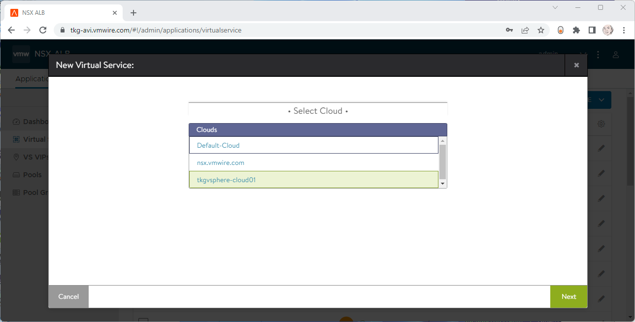
Click on Applications | Virtual Services | Create Virtual Service | Advanced Setup
Select the Cloud to create the DNS virtual service in.
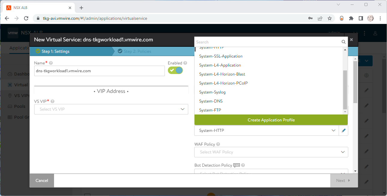
Under Application Profile, select System DNS.
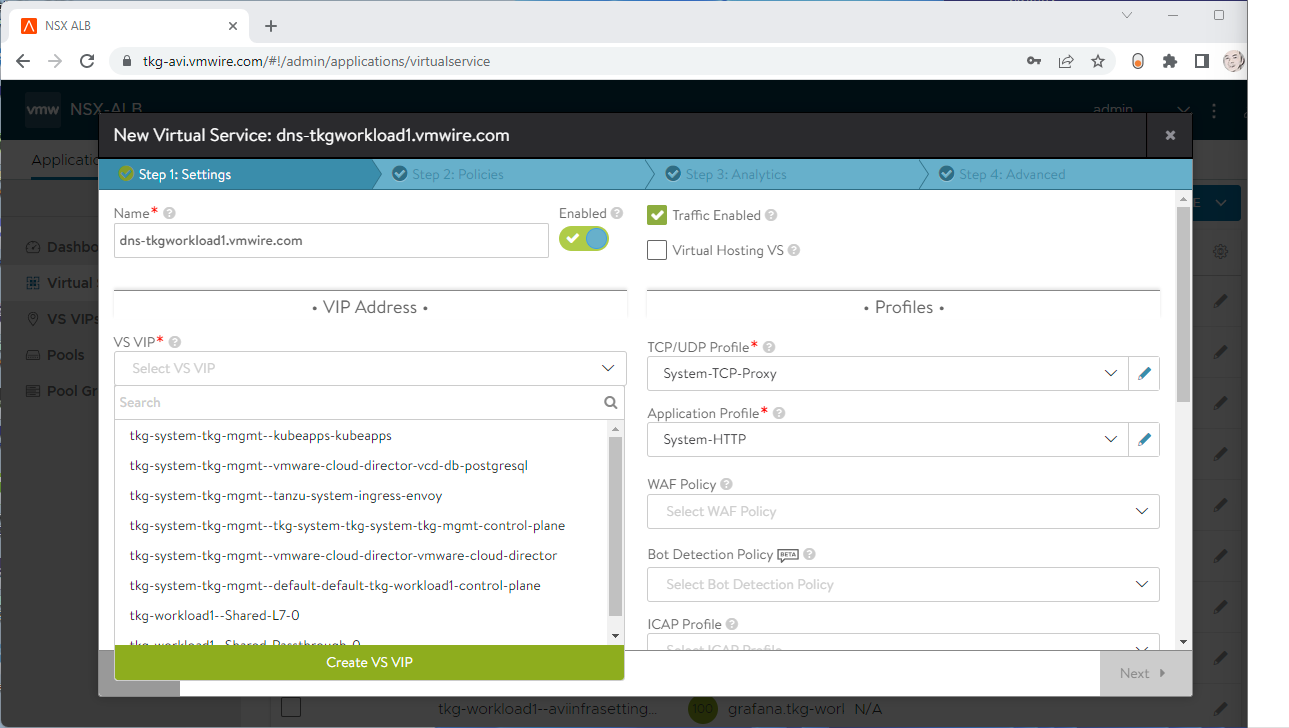
Under VS VIP, click on Create VS VIP.
Press the ADD button under VIPs.
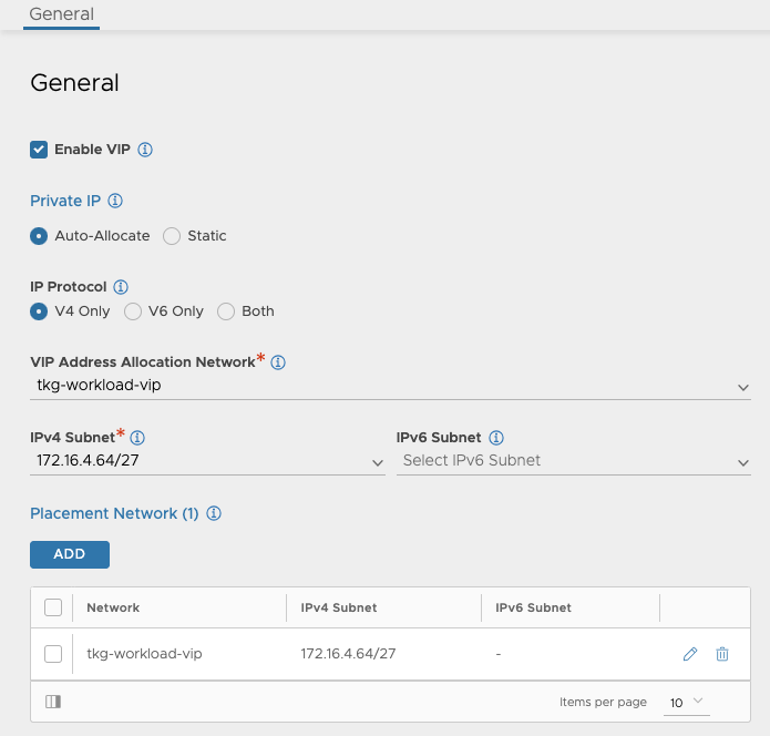
Give the service a name, select a VIP Address Allocation Network, IPv4 Subnet and Placement Network. Don’t set anything for DNS or RBAC.
Then press Save a few times to complete the wizard.
Goto the Advanced tab and choose a Service Engine Group for the DNS service to use.
Press Save to complete the virtual service setup.
Step 2- Enable DNS Service for Avi
Navigate to the Administration tab and select the DNS Virtual Service in the drop-down menu.
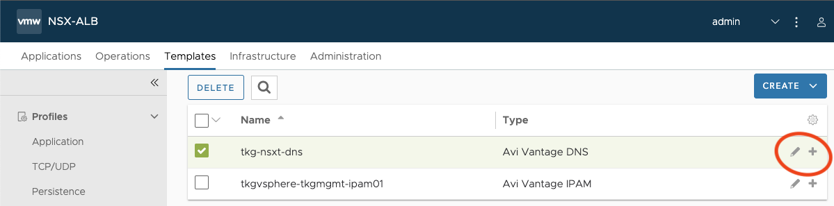
Step 3- Edit the default DNS Profile
Navigate to the Templates tab and edit the default DNS profile, the type is Avi Vantage DNS.
Under DNS Service Domains, add in the domain that you will be delegated by the Avi DNS Service. Then press Save.
Step 4- Edit the default DNS Profile
Navigate to the Infrastructure tab and edit the cloud that you want to enable for Avi DNS.
Click on the IPAM/DNS button at the top and it should take you to that section.
Make sure that the DNS profile is selected under DNS Profile.
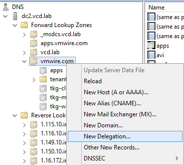
Step 5- Add the Avi DNS Service as a delegated domain in DNS
Find out the IP address of the Avi DNS virtual service, mine is 172.16.4.67.
You can identify it by going to Applications | Virtual Services.
I use Microsoft DNS Services, so using DNS Manager for the DNS Delegation. I want to use *.tkg-workload1.vmwire.com with Avi Ingress, so to delegate the tkg-workload1 domain with Microsoft DNS Services we create a new Delegation.
Enter the IP address for the FQDN.
Thats it!
You’re now ready for Avi to manage DNS records for the sub domain delegation.
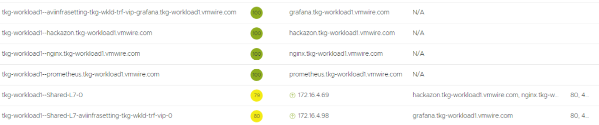
Avi Infra Setting provides a way to segregate Layer-4/Layer-7 virtual services to have properties based on different underlying infrastructure components, like Service Engine Group, intended VIP Network etc.
Here I have a different network that I want a new Ingress to use, in this case the tkg-wkld-trf-vip network, 172.16.4.97/27, lets assume its used for 5G traffic connectivity and the NSX-T T1 is connected to a different T0 VRF. This isolates the traffic between VRFs, so that we can expose certain applications on different VRFs.
In this example, I’ll change Grafana from using the default VIP network to the tkg-wkld-trf-vip network instead. You can read up on how this was originally done using the default VIP network in the previous post.
Avi Infra Settings can be applied to Ingress resources, using the IngressClass construct. IngressClass provides a way to configure Controller-specific load balancing parameters and applies these configurations to a set of Ingress objects. AKO supports listening to IngressClass resources in Kubernetes version 1.19+. The Avi Infra Setting reference can be provided in the Ingress Class as shown below:
The default setting for load balancer service requests for application services defaults to using the two-arm load balancer with NSX Advanced Load Balancer (Avi) in Container Service Extension (CSE) provisioned Tanzu Kubernetes Grid (TKG) cluster deployed in VMware Cloud Director (VCD).
VCD tells NSX-T to create a DNAT towards an internal only IP range of 192.168.8.x. This may be undesirable for some customers and it is now possible to remove the need for this and just use a one-arm load balancer instead.
This capability has been enabled only for VCD 10.4.x, in prior versions of VCD this support was not available.
The requirements are:
CSE 4.0
VCD 10.4
Avi configured for VCD
A TKG cluster provisioned by CSE UI.
If you’re still running VCD 10.3.x then this blog article is irrelevant.
The vcloud-ccm-configmap config map stores the vcloud-ccm-config.yaml, that is used by the vmware-cloud-director-ccm deployment.
Step 1 – make a copy of the vcloud-ccm-configmap
k get cm -n kube-system vcloud-ccm-configmap -o yaml
Make a copy of the config map to edit it and then apply, since the current config map is immutable.
k get cm -n kube-system vcloud-ccm-configmap -o yaml > vcloud-ccm-configmap.yaml
Step 2 – Edit the vcloud-ccm-configmap
Edit the file, delete the entries under data: oneArm:\n , delete the startIP and endIP lines and change the value to true for the key enableVirtualServiceSharedIP. Ignore the rest of the file.
To apply the new config map, you need to delete the old configmap first.
k delete cm -n kube-system vcloud-ccm-configmap
configmap "vcloud-ccm-configmap" deleted
Apply the new config map with the yaml file that you just edited.
k apply -f vcloud-ccm-configmap.yaml
configmap/vcloud-ccm-configmap created
To finalize the change, you have to take a backup of the vmware-cloud-director-ccm deployment and then delete it so that it can use the new config-map.
You can check the config map that this deployment uses by typing:
k get deploy -n kube-system vmware-cloud-director-ccm -o yaml
Step 4 – Redeploy the vmware-cloud-director-ccm deloyment
Take a backup of the vmware-cloud-director-ccm deployment by typing:
k get deploy -n kube-system vmware-cloud-director-ccm -o yaml > vmware-cloud-director-ccm.yaml
No need to edit this time. Now delete the deployment:
k delete deploy -n kube-system vmware-cloud-director-ccm
You can now recreate the deployment from the yaml file:
k apply -f vmware-cloud-director-ccm.yaml
deployment.apps/vmware-cloud-director-ccm created
Now when you deploy and application and request a load balancer service, NSX ALB (Avi) will route the external VIP IP towards the k8s workers nodes, instead of to the NSX-T DNAT segment on 192.168.2.x first.
Step 5 – Deploy a load balancer service
k apply -f https://raw.githubusercontent.com/hugopow/tkg-dev/main/web-statefulset.yaml
You’ll notice a few things happening with this example. A new statefulset with one replica is scheduled with an nginx pod. The statefulset also requests a 1 GiB PVC to store the website. A load balancer service is also requested.
Note that there is no DNAT setup on this tenant’s NAT services, this is because after the config map change, the vmware-cloud-director cloud controller manager is not using a two-arm load balancer architecture anymore, therefore no need to do anything with NSX-T NAT rules.
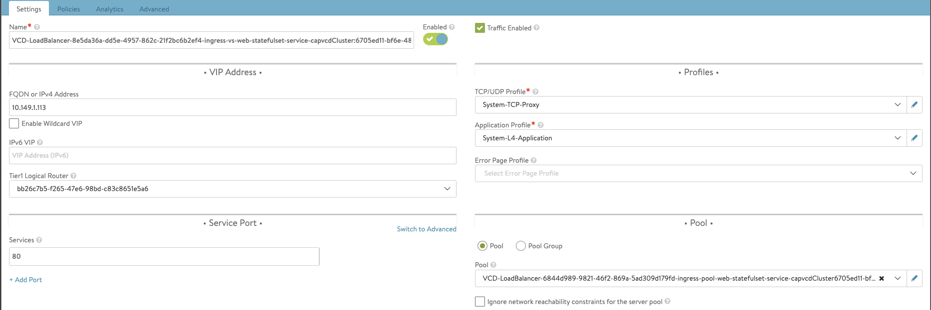
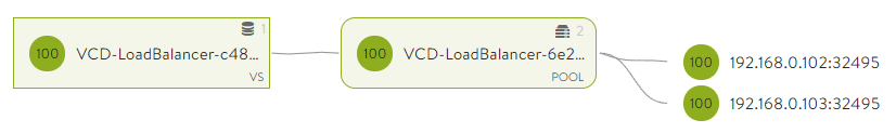
If you check your NSX ALB settings you’ll notice that it is indeed now using a one-arm configuration. Where the external VIP IP address is 10.149.1.113 and port is TCP 80. NSX ALB is routing that to the two worker nodes with IP addresses of 192.168.0.100 and 192.168.0.102 towards port TCP 30020.
k get svc -n web-statefulset
NAME TYPE CLUSTER-IP EXTERNAL-IP PORT(S) AGE
web-statefulset-service LoadBalancer 100.66.198.78 10.149.1.113 80:30020/TCP 13m
k get no -o wide
NAME STATUS ROLES AGE VERSION INTERNAL-IP EXTERNAL-IP OS-IMAGE KERNEL-VERSION CONTAINER-RUNTIME

tkg-1-worker-node-pool-1-68c67d5fd6-c79kr Ready 5h v1.22.9+vmware.1 192.168.0.102 192.168.0.102 Ubuntu 20.04.4 LTS 5.4.0-109-generic containerd://1.5.11
tkg-1-worker-node-pool-2-799d6bccf5-8vj7l Ready 4h46m v1.22.9+vmware.1 192.168.0.100 192.168.0.100 Ubuntu 20.04.4 LTS 5.4.0-109-generic containerd://1.5.11
This article describes how to setup vCenter, VCD, NSX-T and NSX Advanced Load Balancer to support exposing Kubernetes applications in Kubernetes clusters provisioned into VCD.
At the end of this post, you would be able to run this command:
… and have NSX ALB together with VCD and NSX-T automate the provisioning and setup of everything that allows you to expose that application to the outside world using a Kubernetes service of type LoadBalancer.
Create a Content Library for NSX ALB
In vCenter (Resource vCenter managing VCD PVDCs), create a Content Library for NSX Advanced Load Balancer to use to upload the service engine ova.
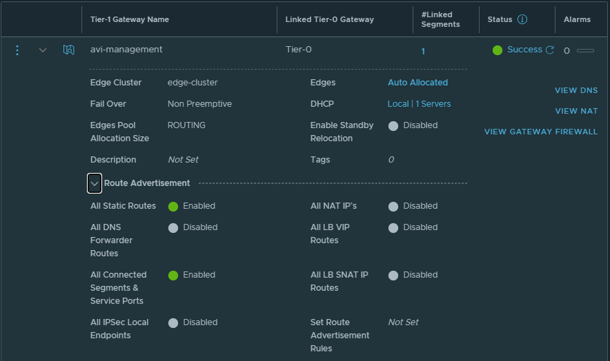
Create T1 for Avi Service Engine management network
Create T1 for Avi Service Engine management network. You can either attach this T1 to the default T0 or create a new T0.
enable DHCP server for the T1
enable All Static Routes and All Connected Segments & Service Ports under Route Advertisement
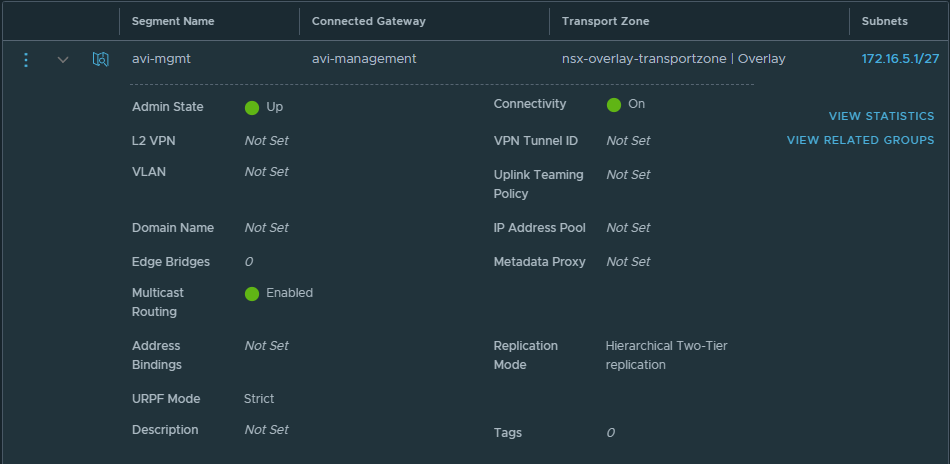
Create a network segment for Service Engine management network
Create a network segment for Avi Service Engine management network. Attach the segment to the T1 the was created in the previous step.
Ensure you enable DHCP, this will assign IP addresses to the service engines automatically and you won’t need to setup IPAM profiles in Avi Vantage.
NSX Advanced Load Balancer Settings
A couple of things to setup here.
You do not need to create any tenants in NSX ALB, just use the default admin context.
No IPAM/DNS Profiles are required as we will use DHCP from NSX-T for all networks.
Use FQDNs instead of IP addresses
Use the same FQDN in all systems for consistency and to ensure that registration between the systems work
NSX ALB
VCD
NSX-T
Navigate to Administration, User Credentials and setup user credentials for NSX-T controller and vCenter server
Navigate to Administration, Settings, Tenant Settings and ensure that the settings are as follows
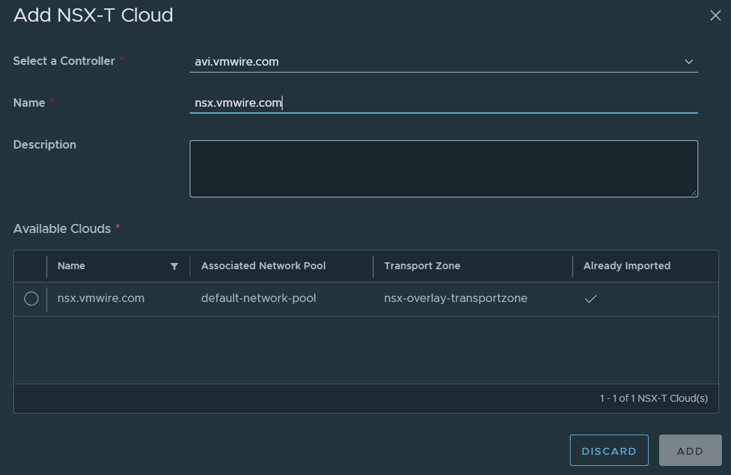
Setup an NSX-T Cloud
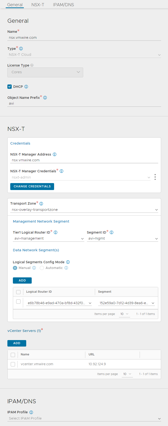
Navigate to Infrastructure, Clouds. Setup your cloud similar to mine, I have valled my NSX-T cloud nsx.vmwire.com (which is the FQDN of my NSX-T Controller).
Lets go through these settings from the top.
use the FQDN of your NSX-T manager for the name
click the DHCP option, we will be using NSX-T’s DHCP server so we can ignore IPAM/DNS later
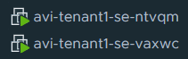
enter something for the Object Name Prefix, this will give the SE VM name a prefix so they can be identified in vCenter. I used avi here, so it will look like this in vCenter
type the FQDN of the NSX-T manager into the NSX-T Manager Address
choose the NSX-T Manager Credentials that you configured earlier
select the Transport Zone that you are using in VCD for your tenants
under Management Network Segment, select the T1 that you created earlier for SE management networking
under Segment ID, select the network segment that you created earlier for the SE management network
click ADD under the Data Network Segment(s)
select the T1 that is used by the tenant in VCD
select the tenant organization routed network that is attached to the t1 in the previous task
the two previous settings tell NSX ALB where to place the data/vip network for front-end load balancing use. NSX-ALB will create a new segment for this in NSX-T automatically, and VCD will automatically create DNAT rules when a virtual service is requested in NSX ALB
the last step is to add the vCenter server, this would be the vCenter server that is managing the PVDCs used in VCD.
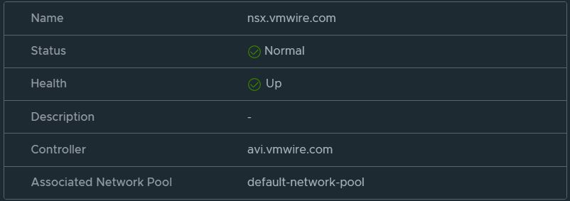
Now wait for a while until the status icon turns green and shows Complete.
Setup a Service Engine Group
Decide whether you want to use a shared service engine group for all VCD tenants or dedicated a service engine group for each Tenant.
I use the dedicated model.
navigate to Infrastructure, Service Engine Group
change the cloud to the NSX-T cloud that you setup earlier
create a new service engine group with your preferred settings, you can read about the options here.
Setup Avi in VCD
Log into VCD as a Provider and navigate to Resources, Infrastructure Resources, NSX-ALB, Controllers and click on the ADD link.
Wait for a while for Avi to sync with VCD. Then continue to add the NSX-T Cloud.
Navigate to Resources, Infrastructure Resources, NSX-ALB, NSX-T Clouds and click on the ADD link.
Proceed when you can see the status is healthy.
Navigate to Resources, Infrastructure Resources, NSX-ALB, Service Engine Groups and click on the ADD link.
Staying logged in as a Provider, navigate to the tenant that you wish to enable NSX ALB load balancing services and navigate to Networking, Edge Gateways, Load Balancer, Service Engine Groups. Then add the service engine group to this tenant.
This will enable this tenant to use NSX ALB load balancing services.
Deploy a new Kubernetes cluster in VCD with Container Service Extension
Deploy a new Kubernetes cluster using Container Service Extension in VCD as normal.
Once the cluster is ready, download the kube config file and log into the cluster.
Check that all the nodes and pods are up as normal.
You might see that the following pods in the kube-system namespace are in a pending state. If everything is already working then move onto the next section.
Wait for the load balancer service to start and the pod to go into a running state. During this time, you’ll see the service engines being provisioned automatically by NSX ALB. It’ll take 10 minutes or so to get everything up and running.
You can use this command to check when the load balancer service has completed and check the EXTERNAL-IP.
kubectl get service webserver
NAME TYPE CLUSTER-IP EXTERNAL-IP PORT(S) AGE
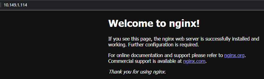
webserver LoadBalancer 100.71.45.194 10.149.1.114 80:32495/TCP 7h48m
You can see that NSX ALB, VCD and NSX-T all worked together to expose the nginx applicationto the outside world.
The external IP of 10.149.1.114 in my environment is an uplink segment on a T0 that I have configured for VCD tenants to use as egress and ingress into their organization VDC. It is the external network for their VDCs.
Paste the external IP into a web browser and you should see the nginx web page.
In the next post, I’ll go over the end to end network flow to show how this all connects NSX ALB, VCD, NSX-T and Kubernetes together.
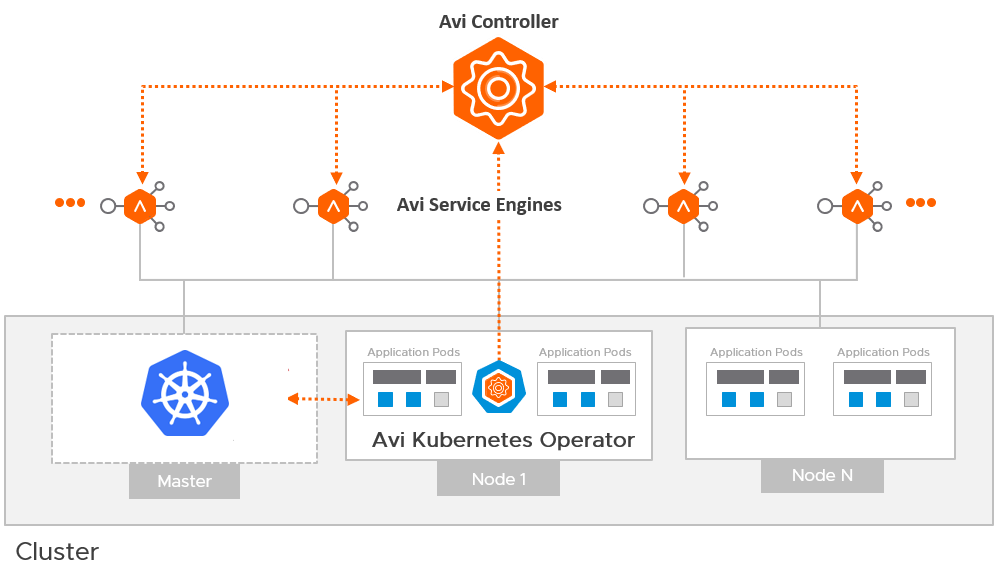
In this post I describe how to setup NSX ALB (Avi) in preparation for use with Tanzu Kubernetes Grid, more specifically, the Avi Kubernetes Operator (AKO).
AKO is a Kubernetes operator which works as an ingress controller and performs Avi-specific functions in a Kubernetes environment with the Avi Controller. It runs as a pod in the cluster and translates the required Kubernetes objects to Avi objects and automates the implementation of ingresses/routes/services on the Service Engines (SE) via the Avi Controller.
Avi Kubernetes Operator Architecture
First lets describe the architecture for TKG + AKO.
For each tenant that you have, you will have at least one AKO configuration.
A tenant can have one or more TKG workload clusters and more than one TKG workload cluster can share an AKO configuration. This is important to remember for multi-tenant services when using Tanzu Kubernetes Grid. However, you can of course configure an AKO config for each TKG workload cluster if you wish to provide multiple AKO configurations. This will require more Service Engines and Service Engine Groups as we will discuss further below.
So as a minimum, you will have several AKO configs. Let me summarize in the following table.
AKO Config
Description
Specification
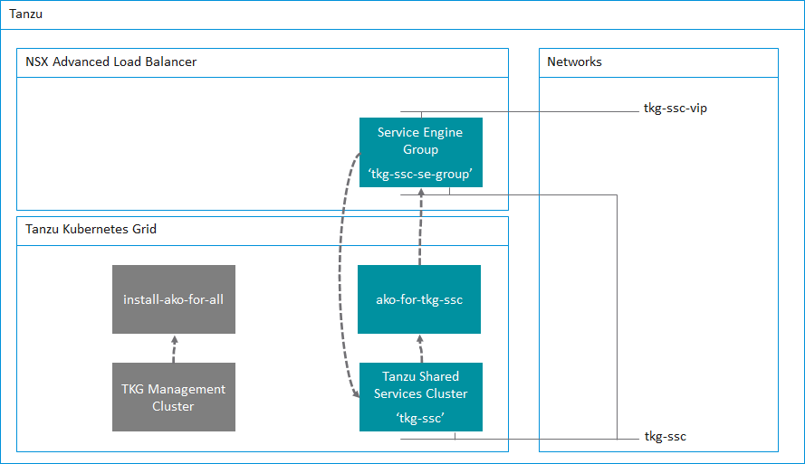
install-ako-for-all
The default ako configuration used for the TKG Management Cluster and deployed by default
Provider side ako configuration for the TKG Management Cluster only.
ako-for-tkg-ssc
The ako configuration for the Tanzu Shared Services Cluster
Provider side AKO configuration for the Tanzu Shared Services Cluster only.
tkg-ssc-akodeploymentconfig.yaml
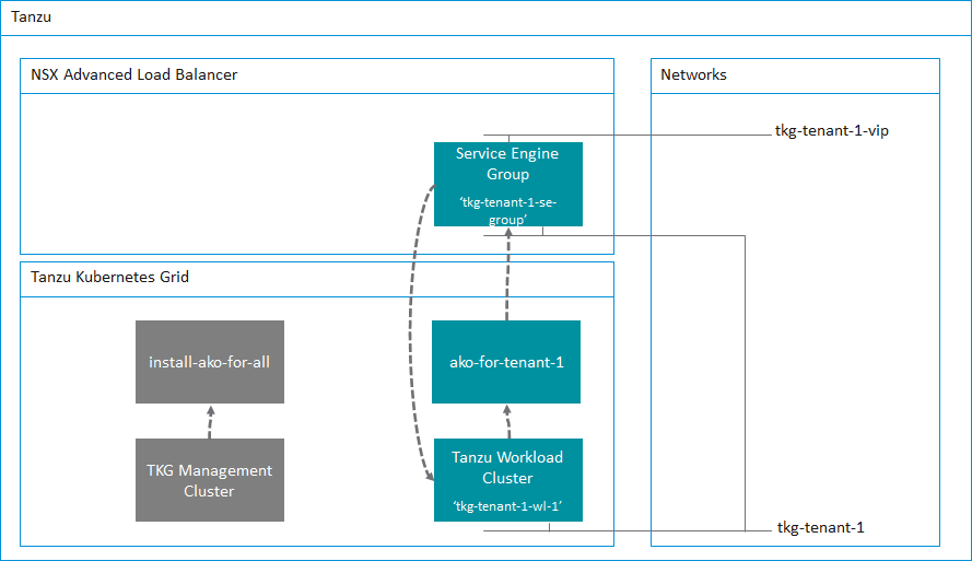
ako-for-tenant-1
The ako configuration for Tenant 1
AKO configuration prepared by the Provider and deployed for the tenant to use.
tkg-tenant-1-akodeploymentconfig.yaml
ako-for-tenant-x
The ako configuration for Tenant x
Although TKG deploys a default AKO config, we do not use any ingress services for the TKG Management Cluster. Therefore we do not need to deploy a Service Engine Group and Service Engines for this cluster.
Service Engine Groups and Service Engines are only required if you need ingress services to your applications. We of course need this for the Tanzu Shared Services and any applications deployed into a workload cluster.
I will go into more detail in a follow-up post where I will demonstrate how to setup the Tanzu Shared Services Cluster that uses the preparation steps described in this post.
Lets start the Avi Controller configuration. Although I am using the Tanzu Shared Services Cluster as an example for this guide, the same steps can be repeated for all additional Tanzu Kubernetes Grid workload clusters. All that is needed is a few changes to the .yaml files and you’re good to go.
Clouds
I prefer not to use the Default-Cloud, and will always create a new cloud.
The benefit to using NSX ALB in write mode (Orchestration mode) is that NSX ALB will orchestrate the creation of service engines for you and also scale out more service engines if your applications demand more capacity. However, if you are using VMware Cloud on AWS, this is not possible due to restrictions with the RBAC constraints within VMC so only non-orchestration mode is possible with VMC.
In this post I’m using my home lab which is running vSphere.
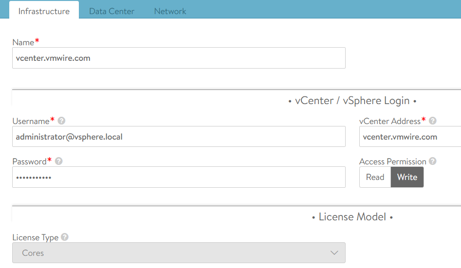
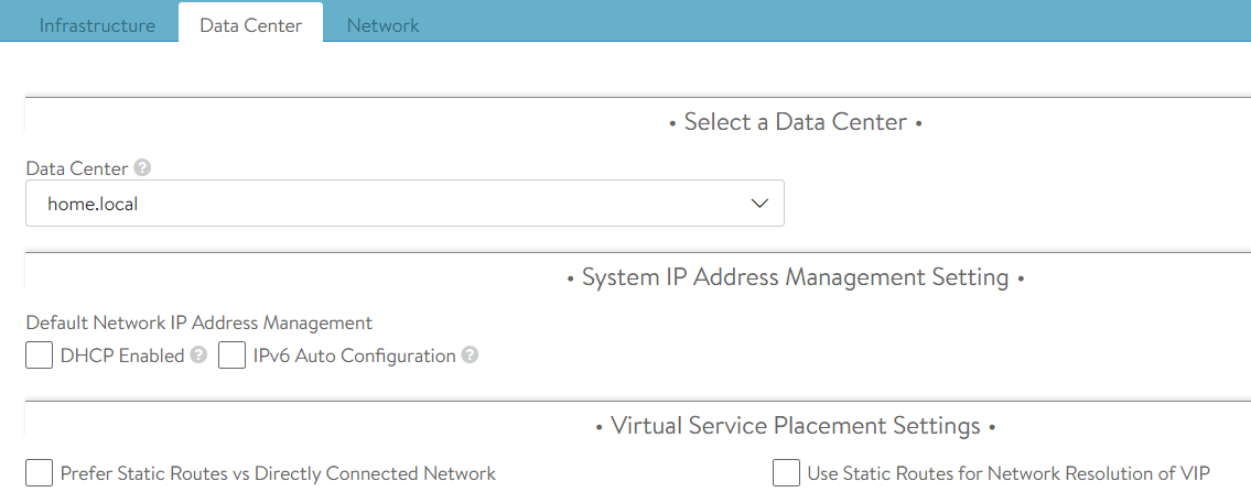
Navigate to Infrastructure, Clouds and click on the CREATE button and select the VMware vCenter/VMware vSphere ESX option. This post uses vCenter as a cloud type.
Fill in the details as my screenshots show. You can leave the IPAM Profile settings empty for now, we will complete these in the next step.
Select the Data Center within your vSphere hierarchy. I’m using my home lab for this example. Again leave all the other settings on the defaults.
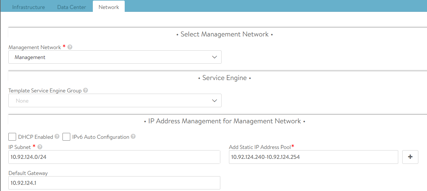
The next tab will take you to the network options for the management network to use for the service engines. This network needs to be routable between the Avi Controller(s) and the service engines.
The network tab will show you the networks that it finds from the vCenter connection, I am using my management network. This network is where I run all of the management appliances, such as vCenter, NSX-T, Avi Controllers etc.
Its best to configure a static IP pool for the service engines. Generally, you’ll need just a handful of IP addresses as each service engine group will have two service engines and each service engine will only need one management IP. A service engine group can provide Kubernetes load balancing services for the entire Kubernetes cluster. This of course depends on your sizing requirements, and can be reviewed here. For my home lab, fourteen IP addresses is more than sufficient for my needs.
Service Engine Group
While we’re in the Infrastructure settings lets proceed to setup a new Service Engine Group. Navigate to Infrastructure, Service Engine Group, select the new cloud that we previously setup and then click on the CREATE button. Its important that you ensure you select your new cloud from that drop down menu.
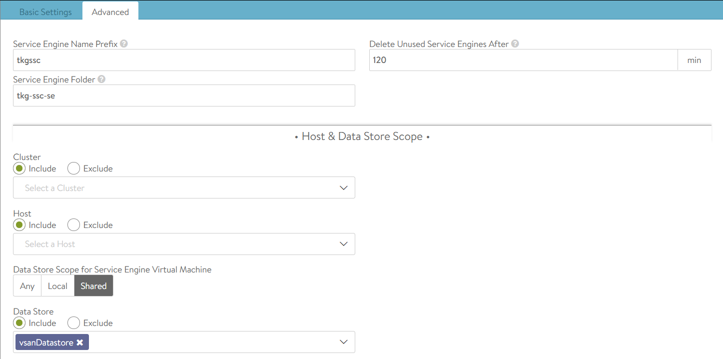
Give your new service engine group a name, I tend to use a naming format such as tkg-<cluster-name>-se-group. For this example, I am setting up a new SE group for the Tanzu Shared Services Cluster.
Reduce the maximum number of service engines down if you wish. You can leave all other settings on defaults.
Click on the Advanced tab to setup some vSphere specifics. Here you can setup some options that will help you identify the SEs in the vSphere hierarchy as well as placing the SEs into a VM folder and options to include or exclude compute clusters or hosts and even an option to include or exclude a datastore.
Service Engine groups are important as they are the boundary with which TKG clusters will use for L4 services. Each SE Group needs to have a unique name, this is important as each TKG workload cluster will use this name for its AKODeploymentConfig file, this is the config file that maps a TKG cluster to NSX ALB for L4 load balancing services.
With TKG, when you create a TKG workload cluster you must specify some key value pairs that correspond to service engine group names and this is then applied in the AKODeploymentConfig file.
The following table shows where these relationships lie and I will go into more detail in a follow-up post where I will demonstrate how to setup the Tanzu Shared Services Cluster.
Avi Controller
TKG cluster deployment file
AKO Config file
Service Engine Group name tkg-ssc-se-group
AVI_LABELS
'cluster': 'tkg-ssc'
clusterSelector:
  matchLabels:
   cluster: tkg-ssc

serviceEngineGroup: tkg-ssc-se-group
Networks
Navigate to Infrastructure, Networks, again ensure that you select your new cloud from the drop down menu.
The Avi Controller will show you all the networks that it has detected using the vCenter connection that you configured. What we need to do in this section is to configure the networks that NSX ALB will use when configuring a service for Kubernetes to use. Generally, depending on how you setup your network architecture for TKG, you will have one network that the TKG cluster will use and another for the front-end VIP. This network is what you will use to expose the pods on. Think of it as a load balancer DMZ network.
In my home lab, I use the following setup.
Network
Description
Specification
tkg-mgmt
TKG Management Cluster
Network: 172.16.3.0/27 Static IP Pools: 172.16.3.26 – 172.16.3.29
tkg-ssc
TKG Shared Services Cluster
Network: 172.16.3.32/27 Static IP Pools: 172.16.3.59 – 172.16.3.62
tkg-ssc-vip
TKG Shared Services Cluster front-end VIPs
Network: 172.16.4.32/27 Static IP Pools: 172.16.4.34 – 172.16.4.62
IPAM Profile
Create an IPAM profile by navigating to Templates, Profiles, IPAM/DNS Profiles and clicking on the CREATE button and select IPAM Profile.
Select the cloud that you setup above and select all of the usable networks that you will use for applications that will use the load balancer service from NSX ALB. You want to select the networks that you configured in the step above.
Avi Controller Certificate
We also need the SSL certificate used by the Avi Controller, I am using a signed certificate in my home lab from Let’s Encrypt, which I wrote about in a previous post.
Navigate to Templates, Security, SSL/TLS Certificates, click on the icon with a downward arrow in a circle next to the certificate for your Avi Controller, its normally the first one in the list.
Click on the Copy to clipboard button and paste the certificate into Notepad++ or similar.
At this point we have NSX ALB setup for deploying a new TKG workload cluster using the new Service Engine Group that we have prepared. In the next post, I’ll demonstrate how to setup the Tanzu Shared Services Cluster to use NSX ALB for ingress services.