Enabling VMXNET 3 for PXEBOOT and KICKSTART of RHEL Virtual Machines

Purpose

This guide shows you how to create a new initrd.img with integration for the VMXNET3 driver to allow guest RHEL virtual machines equipped with the VMXNET 3 driver to Kickstart build RHEL using PXEBOOT.

Background

VMware’s VMXNET 3 network adapter supports PXE booting but RHEL 5 does not have a driver that supports network installations using the default initrd.img.

If you tried to perform automated installation using kickstart with the standard initrd.img you will see the following screen:


This is because Anaconda does not recognise the VMXNET 3 device and therefore is not able to load a driver for it.

This guide shows you how to create a new initrd.img with integration for the VMXNET3 driver.

For the impatient few, I’ve made the resulting initrd.img.vmxnet file available for download, it is a clean ramdisk image that was made using the steps below.

It is the PXEBOOT RAMDISK with the VMXNET3 driver for RHEL5 (created from the rhel-server-5.5-x86_64-dvd) [2.6.18-194.el5].

Tested and working to support VMXNET3 in Anaconda.  You can download it from here initrd.img.vmxnet and then jump all the way to Step 18 to place it on your Build Server.

Prerequisites

Prepare a Reference Virtual Machine

First create a new reference virtual machine with the following hardware specifications:

Configuration Value
VM Hardware Version Hardware Version 7
Network Adapter VMXNET 3
SCSI Controller LSI Logic SAS
SYSTEM .vmdk Device SCSI 0:0 15Gb
Remove Floppy Device Yes

Install RHEL (rhel-server-5.5-x86_64-dvd) by mounting the ISO to the VM and then perform a manual installation of VMware Tools. This will give you the reference virtual machine with which you will then use to copy the vmxnet.ko and vmxnet3.ko from.

Enable sshd services on the Reference VM by typing:

/etc/init.d/sshd start

This will make it a lot easier to copy files to your Build Server.

Prepare your Build Server

Create your own PXEBOOT and Kickstart installation or use one that you already have. For my example I will be using the Ultimate Deployment Appliance 2.0 (uda20.build17).

Most of the configuration is done on Build Server so by all means enable SSHD to make things a lot easier for you.

My Build Server IP is 192.168.200.30.

Integrating VMXNET 3 into initrd.img

At this point you should have SSH access to both your Build Server and your Reference VM.

Perform the following on the Build Server.

1.    Make some working directories to work in

mkdir /tmp/workingdir

mkdir /tmp/workingdir/initrd

mkdir /tmp/workingdir/modules

Perform the following on the Reference VM.

2.    Obtain the initial ramdisk initrd.img from the pxeboot directory, this file can be obtained from the rhel-server-5.5-x86_64-dvd ISO file which should still be connected to the Reference VM. The initrd.img file can be found in the images/pxeboot directory.

3.    Mount the ISO image

mount /dev/cdrom /media

4.    Copy the initrd.img to the Build Server

scp /media/images/pxeboot/initrd.img root@192.168.200.30:/tmp/workingdir/

5.    We now need to ascertain the PCI and Device ID of the VMXNET 3 network adapter by first running

Lspci

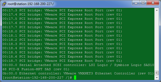
        Note that our VMware VMXNET3 Ethernet Controller lives on 0b:00:0

6.    With this information we can obtain the HEX number for the device by running

lspci –n

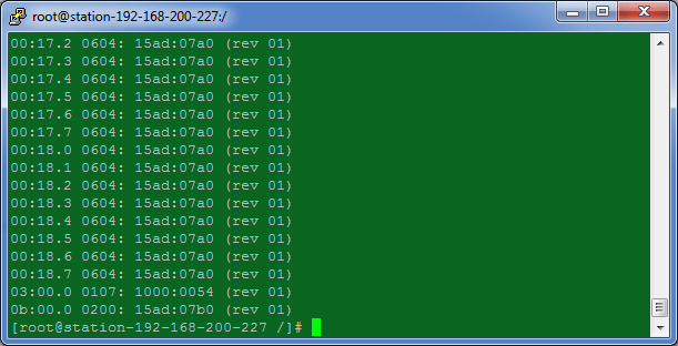
Note the HEX value for device 0b:00.0 is 15ad:07b0.

Perform the following on the Build Server.

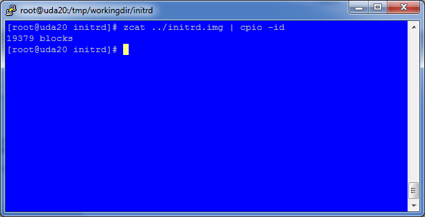
7.    Unpack the initrd.img file to allow us to amend the ramdisk, you should be in /tmp/workingdir/initrd/

zcat ../initrd.img | cpio –id


8.    Extract the modules.cgz archive from within the initrd subdirectory

cd /tmp/workingdir/modules

zcat ../initrd/modules/modules.cgz | cpio –id

Perform the following on the Reference VM.

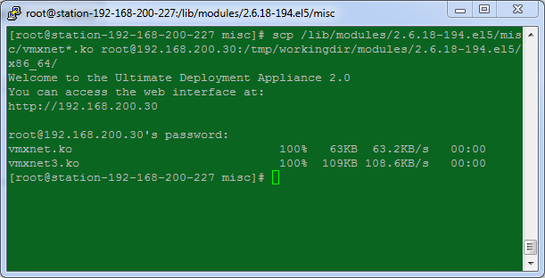
9.    Copy the vmxnet*.ko modules from the Reference VM over to the Build Server. The vmxnet*.ko files are located in /lib/modules/2.6.18-194.el5/misc

scp /lib/modules/2.6.18-194.el5/misc/vmxnet*.ko root@192.168.200.30:/tmp/workingdir/modules/2.6.18-194.el5/x86_64/

10.    Copy the modules.alias file from the Reference VM to the Build Server for use later on. This file contains the vmxnet entries and is located at /lib/modules/2.6.18-194.el5/

scp /lib/modules/2.6.18-194.el5/modules.alias root@192.168.200.30:/tmp/workingdir/initrd/modules/modules.alias.reference

Perform the following on the Build Server.

11.    Change permissions for the two new vmxnet*.ko files, you should be in /tmp/workingdir/modules/2.6.18-194.el5/x86_64/

chmod 744 vmxnet*

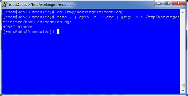
12.    Pack up the new modules.cgz which now includes the vmxnet*.ko modules and create a new cpio archive to replace the old modules.cgz.

cd /tmp/workingdir/modules

find . | cpio -o -H crc | gzip -9 > /tmp/work/initrd/modules/modules.cgz

    After a few seconds the operation will complete.

13.    Modify the pci.ids file with an entry for the VMXNET 3 adapter.

cd /tmp/workingdir/initrd/modules

nano pci.ids

14.    Search for VMware and add the following line under the Abstract SVGA Adapter

07b0    VMware Adapter

    The 07b0 number here is whatever was obtained from Step 5 above.

15.    Edit the module-info file and add the following entries for the VMXNET and VMXNET 3 Adapters, put it in under ‘v’ to keep it in alphabetical descending order. You should still be in /tmp/workingdir/initrd/modules/

nano /tmp/workingdir/initrd/modules/module-info

vmxnet

    eth

    “VMware vmxnet Ethernet driver”


vmxnet3

    eth

    “VMware vmxnet3 Ethernet driver”

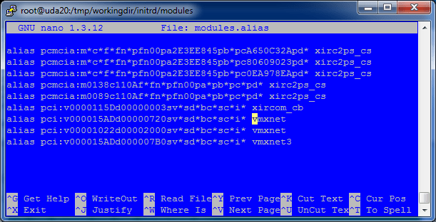
16.    Import the vmxnet entries from the Reference VM’s module.alias file (now called module.alias.reference) into the Build Server’s module.alias file.

grep vmxnet /tmp/workingdir/initrd/modules/modules.alias.reference >> /tmp/workingdir/initrd/modules/modules.alias

The contents of the new module.alias file should look like this.

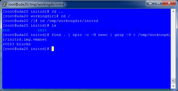
17.    Package the new initrd.img ramdisk up with all the changes done above.

cd /tmp/workingdir/initrd

find . | cpio -o -H newc | gzip -9 > /tmp/workingdir/initrd.img.vmxnet

18.    Copy the new initrd.img.vmxnet into the PXEBOOT environment. On UDA2.0 this location is /var/public/tftproot/

cp /tmp/workingdir/initrd.img.vmxnet /var/public/tftproot/

19.    Edit your PXEBOOT configuration to use the new initrd.img.vmxnet file instead of the standard initrd.img file. My example uses the UDA.

cd /var/public/conf/templates/

nano rhel.dat

20.    On the line CMDLINE=, edit the initrd= entry to point to the new initrd.img.vmxnet instead.

CMDLINE=ks=http://[UDA_IPADDR]/kickstart/[TEMPLATE]/[SUBTEMPLATE].cfg initrd=initrd.img.vmxnet ramdrive_size=8192

21.    That’s it, now PXEBOOT a VM and it will now be able to Kickstart using the VMXNET3 network adapter.

Advertisement

Uninstalling vCD agent on ESXi host

To unistall the vCD agent (vslad) on an ESXi host:

  • Enable Remote Tech Support (SSH) in Configuration | Security Profile | Properties
Enable Remote Tech Support (SSH)
  • Log into the ESXi host using your favourite SSH client
  • Navigate to /opt/vmware/uninstallers
  • Now run the script named vslad-uninstall.sh, or you could just do the below after logging into the ESXi host

/opt/vmware/unistallers/vslad-uninstall.sh

  • Disable Remote Tech Support (SSH)
  • Restart your ESXi host.

Incorrectly configured URL for Organisation in vCloud Director 1.0

VMware vCloud Director (vCD) automatically creates a URL for each organisation that is created in vCD.  There is a slight bug which does not create the URL properly and will cause the URL that is displayed under Customer | Administration | Settings | General to be incorrect.

For example, if you create an organisation called Customer1, the default URL that is created will be:

https://url.of.your.cloud/org/Customer1/

This is of course wrong and if you clicked on the link you would see a page similar to this:

Incorrect URL
Organisation URL Error

So how do we fix this?

Simple, just add cloud into the URL so the new URL will be:

https://url.of.your.cloud/cloud/org/Customer1/

This WILL work but you will have to do this for every new customer and also remember to publish the correct URL.

However, there is a better way, being much more intelligent, amend the system VCD public URL under System | Administration | System Settings | Public Addresses

vCD Public URL
vCD Public URL

This will automatically add cloud into all organisation VCD public URLs.

vShield Manager Notes

Most administrative changes to vShield Manager can be done using the command line interface (CLI) by initiating a console session to the vShield Manager virtual machine.  You can log in to the CLI by using the default user name admin and password default.

You can also access the CLI by enabling SSH.

To enable SSH:

  • Log in to the CLI by using the default user name and password
  • Enter configuration mode by typing

manager# en

manager# configure terminal

manager(config)# ssh start

manager(config)# cli ssh allow


To change the hostname of vShield Manager

vShield Manager uses manager as the default hostname but there is no easy way to change the hostname using the web interface or the vSphere plugin.  You can only change vShield Manager’s hostname using the CLI.

  • Log in to the CLI by using the default user name and password
  • Enter configuration mode by typing

manager# en

manager# configure terminal

manager# hostname newhostname

  • vShield will then restart its web services and accept the changes


More to follow….

Creating a VMware vCloud Director Cluster

Overview

A VMware vCloud Director (vCD) cluster contains one or more vCD servers, these servers are referred to as “Cells” and form the basis of the VMware cloud.  A cloud can be formed of multiple cells. 

This diagram is a good representation of the vCD Cluster concept.

To enable multiple servers to participate in a cluster, the same pre-requisites exist for a single host as for multiple hosts but the following must be met:

  • each host must mount the shared transfer server storage at $VCLOUD_HOME/data/transfer, this is typically located in /opt/vmware/cloud-director/data/transfer.

This shared storage could be a NFS mount, mounted to all participating servers with rw access for root.  It is important that prior to configuring the first server, a decision must be made on whether a cluster is required.  If you intend to use a vCD Cluster, configure the shared transfer server storage before executing the vCD installer.

Check out the vCloud Director Installation and Configuration Guide for pre-requisites.

Shared Transfer Server Storage

For this post, I’ve setup an NFS volume on Freenas and given rw permissions for all cluster members to the volume.  It is assummed that you have a completely clean installation of RHEL 5 x64 (or if like me you are running this in a lab CENTOS 5 x64), with all the latest updates and pre-requisite packages.

Now to mount the volume on all hosts:

  1. Connect to your first host using SSH or login directly
  2. Edit your /etc/fstab file and add the following line remembering to change to your NFS server and relevant mount point
  3. vcd-freenas.vmwire.local:/mnt/SSD /opt/vmware/cloud-director/data/transfer nfs rw,soft,_netdev  0 0
  4. The resulting /etc/fstab should look something like this:
  5. /etc/fstab

    /etc/fstab

  6. Now create the shared transfer server storage folder structure, /opt/vmware/cloud-director/data/transfer (just do a mkdir command)
  7. run chkconfig netfs on
  8. Repeat steps 1-6 for any other hosts
  9. Restart servers

 Now you are ready to install vCD onto the first host, making sure that you have met all the pre-requisites as detailed in the vCloud Director Installation and Configuration Guide.  Once completed you should have a working cell with its shared transfer server storage folder located on the NFS volume.

Setting up a second cell as part of the Cloud Director Cluster

At this point you should already have a working cell with the vCD shared transfer server storage located on the NFS volume.  Before you install vCD onto a server the following must be done:

  1. All pre-requisites for a single server installation must also be met for subsequent servers as part of a vCD Cluster
  2. The second server must also have rw access for root to the shared transfer server storage
  3. The second server must have access to the response file, this file is located in /opt/vmware/cloud-director/etc/responses.properties on the first successfully installed server
  4. Copy the above file to the second server or to the shared transfer server storage
  5. It is important to note that the response file contains values that were used for the first server.  Subsequent servers will use the response file, and as such if you stored your certificates.ks file for the first server in a location not recognised by subsequent servers, you will be prompted by the installation script to enter the correct path to the certificates.ks file for any subsequent servers.  To avoid this, you could create all the certificates.ks files for all cluster members and place them in the shared transfer server storage, with of course unique names such as vcd-cell1-certificates.ks and vcd-cell2-certificates.ks.
  6. You can now install vCD onto subsequent servers with the command vmware-cloud-director-1.0.0-285979.bin -r /opt/vmware/cloud-director/data/transfer/responses.properties

The installer will automatically complete most prompts for you, but you will still need to select the correct eth adapter for the http and consoleproxy services, everything else will be automatic.

Go ahead and have a play and maybe even deploy a load balancer on top.

Here’s a screenshot of my two cells working side by side connecting to the same shared transfer server storage, oracle database and managing the same vCenters.

For more information read the overview at Yellow Bricks which also includes links to the product pages.

Configuring an IBM BladeCenter H with the HS22/HS22v for 6 Nics and 2 FC HBAs

Introduction

Configuring an IBM BladeCenter H chassis to accommodate six network cards and two fiber channel ports can be a little confusing with the amount of ports available for use at the rear of the H chassis.

The rear of the H Chassis looks like this.

IBM H Chassis Rear

There are a total of 10 interconnect bays.  The vertical bays (Bays 1- 6) are normally referred to as Standard Switch Modules and the horizontal ones (Bays 7-10) are referred to as High Speed Switch Modules.

To utilise the horizontal bays, the Multi Switch Interconnect Module (MSIM) modules are required.  What this does is it allows the vertical modules to be installed into bays 7-10.  One MSIM modules occupies both bays 7 and 8, or both bays 9 and 10 simultaneously, allowing for two interconnect modules to be installed within a single MSIM module.

Configuring the HS22/HS22v

The IBM HS22/HS22v server supports two processors, 12 DIMM slots (18 slots for HS22v), two SAS drive bays (two SSD for HS22v), has two onboard network adapters, an internal USB port (for ESXi) and two daughtercard ports – CIOv and CFFh.  Similar to how HP C Class blades terminate the network and fiber ports, the HS22/HS22v also has terminations set via the BladeSystem back-plane and this results in a set configuration of the location of the interconnect modules in the rear of the blade chassis.

The HS22/HS22v’s onboard network adapters, always terminate in bays 1 and 2 of the IBM BladeCenter H chassis.

The CIOv daughtercard will terminate in bays 3 and 4, as any CIOv card will always have a maximum of 2 ports.  Some of the dual port CIOv cards available are:

CIOv Options

The CFFh card is different depending on the exact type of card that is selected.  Any dual port CFFh port will terminate in bays 7 and 8, but any quad port CFFh card will terminate in bays 7, 8 and also 9 and 10.

Some of the CFFh cards available are:

CFFh Options

Of course as stated above, to utilise a CFFh daughtercard, the MSIM module will need to be installed first.  One MSIM module in bays 7 and 8 for a dual port CFFh card and two MSIM in bays 7 and 8 and 9 and 10 for a quad port CFFh card.

For this configuration though I will use the “Ethernet Expansion Card (CIOv) for IBM BladeCenter – CIOv” and the “QLogic Ethernet and 8Gb Fibre Chanel Exp Card (CFFh) for IBM BladeCenter – CFFh”.

This allows us to meet our 6 NIC and 2 HBA requrements.

HS22/HS22v I/O to BladeCenter H I/O Port Mappings

The table below shows how the adapters within the HS22/HS22v terminate at the rear of the H Chassis.

Adapter Net/Fiber H Chassis Bay
Onboard1 Network 1
Onboard2 Network 2
CIOv1 Network 3
CIOv2 Network 4
CFFh1 Network 7
CFFh2 Fiber 8
CFFh3 Network 9
CFFh4 Fiber 10

This diagram also shows how the adapters within the HS22/HS22v terminate at the rear of the H Chassis.

HS22 IO Ports to BladeCenter H

So there you have it, the HS22/HS22v in a BladeSystem H simplified.


Tech Tip: How to fix the dynamic disk problem after a P2V

The scenario:

A customer has a non-critical HP server that they would like to P2V. It is installed with 2 x SATA disks without a SATA RAID controller, runs Windows Server 2003 and uses software RAID 1 mirror over the two disks which are set as dynamic. On top of this, the mirrored disks are split into two logical partitions, C: and D:.
Breaking the mirror and performing a hot P2V using VMware Converter 4.0 Standalone, with the two volumes being P2V’d into two separate .VMDK files fails at 95% during the reconfiguration phase.
If you receive a failure at 95%, it just means that the reconfiguration has failed due to VMware Converter not being able to find the system partition, that actual data copy has successfully completed and the data is intact. Obviously the virtual machine will not boot so how can we fix this?
The solution:
  1. Boot the virtual machine, select F2 to go into the virtual machine’s BIOS and make sure that the VM is booting from the correct virtual disk.
  2. Boot the machine into a disk management software like Acronis Disk Director Suite or similar and convert the partitions from logical to primary partitions and then select the C: partition as the active partition.
The virtual machine will now boot successfully.

Change Evolution is ‘The Way’

I’m working on a paper, document, anything, (probably just this post now since my schedule is so busy) on something that’s been in the back of my mind for a while now, and every time I speak to a new opportunity or a customer I always wished that I had something substantial to leave behind to show that yes, it is possible to achieve the desired future state without pain.

What I’m talking about is how to get from A to Z without pain, fear, risk, or increased cost and time.

‘A to Z’ is an expression that we all use, but in Lehmann’s terms it is getting to the desired future state from the current state.

What is the future state? For example a server migration project of 1000 Wintel servers into VMware infrastructure in 6 months.

So if A is the origin and Z is the destination, then the journey of getting from A to Z is the experience. It is the experience that is all too important. In a project’s lifecycle, the primary purpose of a project is to bring benefit to something (an organisation for example). But the experience can vary dramatically. Z can be achieved but at what cost? Z can be achieved but it could take a long time. Z can also be achieved but after how many mistakes, issues and actions that were required to achieve Z?

Is there a way to define the experience? To reduce the amount of risk and unplanned change, to limit the exposure to mistakes and unknowns. To cap the amount of time and cost to achieving Z. ‘The Way’ then is called a methodology. A methodology is a collection of processes and frameworks which are used to control the execution of change within a project.

So while I’m in a pessimistic mood, let’s go over why there are difficulties from having a comfortable journey:
• Lack of planning
• Lack of clear objectives
• Lack of support and acceptance (See Steve Chamber’s Barriers to Virtualisation)
• Lack of risk management
• Lack of a business case or project justification
• Lack of change control

Why is change so feared?

Let’s assume that your project justification and initiation are all good and that your project plans, objectives, business case and RAID are all up to scratch and now you are ready to embark on a project that changes your IT infrastructure. Have you considered how you will manage change? Are there push backs from the business or application owners who don’t really need or want anything to happen to their precious server due to changing the way a workload is run?

How can you alleviate their fears and introduce controlled change?

So let’s take the classic CIO/IT Director from a few years ago at a time when x86 consolidation using virtualisation was still in its infancy (there are those that still think transitioning to a virtual infrastructure is a risk too far). These CIOs had fears around change – change of management, change of skills, change of processes and changes with operations. These fears were prevalent then and are still prevalent now. In my view the main enablers for change are the frameworks that can be used to get from A to Z.

Without change, an IT organisation will never be able to evolve into an IT organisation that has more reliable infrastructure, more efficient processes and more streamlined operations. Those companies that do embrace change and evolve are considered to be the most high performing IT Organisations.

The consensus is basically this: change causes fear, therefore projects such as P2V take forever to do, and without the correct methodology your P2V project could fail before it has actually begun. But by introducing controlled change and then putting the processes and governance in place; the strategy controls, manages change and provides a framework for effective management and delivery of the project.

The barrier to evolution is due to a fear of change, we alleviate this fear by controlling change. Change then becomes the enabler for evolution: please welcome Change Evolution.

So what is Change Evolution?

Change Evolution is a framework that uses ITIL/Visible Ops methodologies to control migration to virtualisation projects. It expedites ROI due to enablement of change management as part of BAU/Operations.

Change Evolution is a framework for delivering projects with

  • less Risk
  • less Time
  • less Cost

How is this accomplished?

  1. With baselined standard operating environments (SOE) which are standardised and adhere to strict change control.
  2. With Standard Operating Procedures (SOP) which are auditable, repeatable and measurable and are strictly controlled. Because these procedures are defined and controlled as part of the framework, it is possible for any member of the project to use these procedures to assist with the grunt work of the project. These procedures enable the ‘turning the handle’ method of migrations where the migrations are streamlined into the control processes.
  3. By working closely with the change control board (CCB). It is strategic to keep the CCB on your side, we are not re-inventing the wheel with change boards, we embrace them, but the amount of requests is submitted in a ‘turning the handle’ method in which P2V migrations are requested weeks in advance and each one follows the same migration methodology, processes and SOPs. Therefore these migrations can actually be integrated into operations quicker and with no risk.

By using a defined methodology that integrates with the change control processes it is possible for you to 
deliver 
record‐breaking 
project 
successes 
without
 risk 
and within 
strict
 time scales
 and
 budgets and above all with no pain.

Power CLI Quick Start Guide

1. INTRODUCTION

1.1 Overview

The VI Toolkit (for Windows) provides a powerful yet simple command line interface for task based management of the VMware Infrastructure platform. Windows Administrators can easily manage and deploy the VMware Infrastructure with a familiar, simple to use command line interface.

The VI Toolkit (for Windows) is a tool that system administrators and developers can use to automate the management of VMware Virtual Infrastructure. With the VI Toolkit (for Windows), many tedious and time-consuming tasks can be completely automated in as little as one line of code.

The VI Toolkit (for Windows) takes advantage of Windows PowerShell and .NET to bring unprecedented ease of management and automation to the Virtual Infrastructure platform. The VI Toolkit (for Windows) provides 125 PowerShell cmdlets that cover all aspects of Virtual Infrastructure management.
Some common tasks that the VI Toolkit (for Windows) can be used to perform include:

  • Snapshoting all virtual machines.
  • Disconnecting or removing all Floppy or CD-ROM drives from all Virtual Machines.
  • Large-scale cloning of templates.
  • Moving large numbers of Virtual Machines from one virtual switch to another.
  • Migrating large numbers of Virtual Machines between ESX hosts.
  • Reports and monitoring across the entire Virtual Infrastructure.

1.2 System Requirements

The following platforms are supported by the VI Toolkit (for Windows):

  • Microsoft Windows Server 2003 R2 (32 or 64 bit)
  • Microsoft Windows Server 2003 with Service Pack 2 (SP2) (32 or 64 bit)
  • Microsoft Windows Server 2003 with Service Pack 1 (SP1) (32 or 64 bit)
  • Microsoft Windows XP with Service Pack 2 (SP2) (32 or 64 bit)
  • Microsoft Windows Vista (32 or 64 bit)

1.3 Virtual Infrastructure Platforms Supported

The following platform combinations are supported by the VI Toolkit (for Windows):

  • Management of ESX 3.0.2 using Virtual Center 2.5
  • Management of ESX 3.5 using Virtual Center 2.5
  • Management of ESXi 3.5 using Virtual Center 2.5
  • Direct management of ESX 3.0.2
  • Direct management of ESX 3.5
  • Direct management of ESXi 3.5

1.4 Pre-requisites

The following tables lists the software pre-requisites and the location to each installer. This guide focuses on the most recent releases as dated 05/02/2009, which are Windows PowerShell V2 CTP3, VI Toolkit (for Windows) version 1.5 and the VI Toolkit Community Extensions build 46896.

Windows PowerShell
VI Toolkit (for Windows)
VI Toolkit Community Extensions

Another pre-requisite that is also recommended for general administration is Notepad++. This is used to create and edit scripts that can be run with the VI Toolkit.
Notepad++ can be downloaded from here.

2. INSTALLATION

There are three installation tasks that need to be performed before you can start using the VI-Toolkit to manage a VMware Infrastructure.

Windows PowerShell. The VI Toolkit 1.5 (for Windows) requires Microsoft PowerShell V2 CTP 3.

Please download it from here.

VI Toolkit (for Windows). Can be downloaded from here.

VI Toolkit Community Extensions. Can be downloaded from here.

3. SETTING UP THE VI TOOLKIT

The procedures below go through in detail how to get the VI-Toolkit up and running after installation. Once installed the icon below will be available on the Windows Desktop.

DO NOT LAUNCH IT YET!

Before launching the VMware VI Toolkit application, you must first set up your PowerShell profile. The new desktop shortcut does two things for you: it starts powershell with the VI Toolkit snapin loaded and it runs a script which modifies the look of the Powershell window and adds some cool extra functions. If you want to have the same functionality in your normal Powershell window and your scripts, you have to copy some stuff to your Powershell profile.

3.1 First, set up your profile:

1. Start a normal PowerShell Window by navigating to Start | All Programs | Windows PowerShell V2 (CTP3) | Windows PowerShell V2 (CTP3), the following will be launched:

2. Run the following command:
Test-Path $profile

3. If it returned True then you already have a profile file. If it returned False, then proceed to the next step.

4. Create a profile file by running:
New-Item $profile –ItemType File

5. If an error is returned then create a WindowsPowerShell directory under your My Documents folder and then repeat step 4.

3.2 Adding the snap-in:

1. Open your profile by running:
Invoke-Item $profile

2. Add the following line to the profile file to load the snap-in:
Add-PSSnapIn VMware.VimAutomation.Core -ErrorAction SilentlyContinue

3.3 Adding undocumented functions

1. Open the file C:\Program Files\VMware\Infrastructure\VIToolkitForWindows\Scripts\Initialize-VIToolkitEnvironment.ps1

2. Copy the following Function Blocks to your profile file:
Get-VICommand, New-DatastoreDrive, New-VIInventoryDrive, Get-VIToolkitDocumentation, Get-VIToolkitCommunity

If the steps were performed successfully, then your profile will be present in the folder structure C:\Documents and Settings\Hugo Phan\My Documents\WindowsPowerShell/ Microsoft.PowerShell_profile.ps1

And its contents will look something like this:

3.4 Enabling the execution of scripts

The Set-ExecutionPolicy changes the user preference for the execution policy of the shell. The execution policy is part of the security strategy of Windows PowerShell. It determines whether you can load configuration files (including your Windows PowerShell profile) and run scripts, and it determines which scripts, if any, must be digitally signed before they will run.

You need to set the execution policy to unrestricted using the below cmdlet

set-executionpolicy unrestricted


get-executionpolicy
will return the current execution policy.

The default ExecutionPolicy is Restricted. Unrestricted is unnecessarily risky.

Set-ExecutionPolicy RemoteSignedis more secure and works for VI Toolkit 1.5.

3.5 Loading the Community Extensions

The VI Toolkit for Windows Community Extensions is a PowerShell module designed to work with the VI Toolkit for Windows.

1. Download and extract the package and then copy the coreModule folder to the root of C:

2. Open up a Windows PowerShell session and then type in the following command
Import-Module “c:\coreModule\viToolkitExtensions.psm1”

Now you are ready to start using the VI Toolit by either logging into a vCenter environment or by launching scripts.

Upgrading to VMware vSphere using the vSphere Host Update Utility

There are three ways in which to upgrade to VMware vSphere, these are

  1. VMware Update Manager
  2. vSphere Host Update Utility 4.0, and
  3. a clean install of vSphere

This post goes through the upgrade process using the vSphere Host Update Utility 4.0. A 10 minute video is available here:

The vSphere Host Update Utility 4.0 is an application that is installed as part of the vSphere vCenter installation package.

  1. To start the upgrade process, launch the vSphere Host Update Utility.
  2. The vSphere Host Update Utility will request confirmation to connect to the VMware patch repository.
  3. Add the host to the update utility by clicking on Host | Add Host.
  4. Type in the FQDN or IP address of the host you wish to upgrade then click on Add.
  5. Now click on the Upgrade button to start the upgrade wizard.
  6. Next browse to the location of your vSphere ISO file then click on Next.
  7. Read and accept the license agreement to continue.
  8. Enter the root credentials then press Next.
  9. The Host compatibility check will perform some checks and will allow the upgrade to continue if the host meets the criteria.
  10. Next select a local datastore (recommended) to store the disk file for the Console OS and also select the disk size.
  11. Leave all other settings on default and finish the Wizard
  12. Once complete, reconnect the host in vCenter to install the new vCenter Agent.

Disaster Recovery just got "sESXi"


Notes on using vRanger Pro & ESXi for Disaster Recovery

Just succesffully proved vRanger Pro to restore backups taken from Production (ESX 3.5, vRanger Pro on physical with VCB) to infrastructure in DR (ESXi 3.5, vRanger Pro on a VM, non VCB). All this from provisioning DR Infrastructure (ESXi Servers, Storage, vCenter VM) within 1 hour. Silver tier recovery just got “sESXi”!

Infrastructure at Production

  • ESX 3.5 Update 2 on BL460C
  • Storage on 400Gb LUNs presented by IBM SVC
  • VC 2.5 Update 2 VM
  • vRanger 3.8.2.1 & VCB 1.5 & vRanger Pro VCB Plugin 3.0 on Physical DL380 G5 Server
  • VM backups on TSM and replicated to DR

Infrastructure at DR

  • ESXi Update 3 USB on DL360 G5
  • Local Storage
  • VC 2.5 Update 4 VM
  • vRanger 3.2.9.7 & VCB 1.5 & vRanger Pro VCB Plugin 3.0 on W2K3 SP2 VM + .Net Framework 2.0 SP1

Important points to note

If you are running vRanger in a virtual machine to restore workloads backed up by vRanger installed on a physical host, with either traditional LAN based backup or VCB based backup. It is important that the software is installed in the correct order and all the necessary software is installed to enable vRanger to restore both types of backup. If the physical vRanger server performed a backup of a workload using the VCB framework, then you will not be able to restore that workload using another vRanger server unless the VCB framework is also installed. For example, you wish to perform a restore at a DR site.

The correct installation order is

  • Microsoft .Net Framework 2.0 SP1
  • vRanger Pro
  • vRanger Pro VCB Integration module
  • vRanger Pro file-level plugin
  • VMware VCB Framework

Tips

  • Install software in the correct order
  • Create the same directory structure for the VM at the DR site as it is at Production. E.g, if the vRanger working directory is D:\vRanger_Backups at Production, then keep the same directory structure for the vRanger server at DR.
  • This will enable you to first restore the vRanger database (esxRanger.mdb), which then populates the Restore table saving valuable time and effort because you will no longer need to use “Restore from Info”
  • If restoring a vRanger backup that was taken using the VCB framework, then the vRanger server at DR will also need to have the VCB framework installed.

What to do when an ESX host shows not responding?

Steps in order to progress

1) Login in the affected ESX server using Putty

2) service mgmt-vmware restart

If this doesn’t work then the vmware-hostd daemon has to be killed.

3) ps -e | grep vmware-hostd
Look for the process_id associated with vmware-hostd

4) kill process_id
i.e. if 3) returned:
32470 ? 00:01:12 vmware-hostd
the command would be:
kill 32470

5) service mgmt-vmware status
if the service is started use
service mgmt-vmware restart
if it’s stopped use:
service mgmt-vmware start

Using ESX 3.5 vmware-vim-cmd instead of vimsh

vmware-vim-cmd

For those of you familiar with vimsh and used it to configure a scripted install of ESX 3.5, have you noticed that the following error would occur when launching commands using /usr/bin/vimsh ?

/usr/bin/vimsh -n -e “hostsvc/maintenance_mode_enter

Alternatively, by using the wrapper developed for ESX 3.5, vmware-vim-cmd, you would get the following:

/usr/bin/vmware-vim-cmd hostsvc/maintenance_mode_enter

The two commands are detailed in the Xtravirt whitepapers, vimsh and vimsh for ESX 3.5. I would recommend at least having a quick browse to see what can be achieved with these commands. Using vmware-vim-cmd in conjunction with esxcfg- can achieve some very interesting results, especially if you love to create the perfect KickStart build script.

If only it is possible to launch vmware-vim-cmd commands using the RCLI just as esxcfg- can be launched using vicfg-. Anyone have an idea?

A few more examples

Refreshing the network settings
/usr/bin/vmware-vim-cmd hostsvc/net/refresh

Refreshing the storage
/usr/bin/vmware-vim-cmd hostsvc/storage/refresh

The all important enabling VMotion
/usr/bin/vmware-vim-cmd hostsvc/vmotion/vnic_set vmk0

And how about setting vSwitch1 to use Route Based on IP Hash?
/usr/bin/vmware-vim-cmd hostsvc/net/vswitch_setpolicy –nicteaming-policy=loadbalance_ip vSwitch1

And setting vSwitch0 to use Route Based on the Originating Virtual PortID. (vSwitch0 has two portgroups using VLAN tagging, 1 for Service Console and 1 for VMotion, we wish to use active-passive nic teaming policy)

Set active vmnic0 and standby vmnic2 for Service Console
/usr/bin/vmware-vim-cmd hostsvc/net/portgroup_set –nicorderpolicy-active=vmnic0 vSwitch0 ‘Service Console’
/usr/bin/vmware-vim-cmd hostsvc/net/portgroup_set –nicorderpolicy-standby=vmnic2 vSwitch0 ‘Service Console’

Set active vmnic2 and standby vmnic0 for VMkernel network
/usr/bin/vmware-vim-cmd hostsvc/net/portgroup_set –nicorderpolicy-active=vmnic2 vSwitch0 VMkernel
/usr/bin/vmware-vim-cmd hostsvc/net/portgroup_set –nicorderpolicy-standby=vmnic0 vSwitch0 VMkernel

Set vSwitch overide load balancing policy
/usr/bin/vmware-vim-cmd hostsvc/net/portgroup_set –nicteaming-policy=loadbalance_srcid vSwitch0 ‘Service Console’
/usr/bin/vmware-vim-cmd hostsvc/net/portgroup_set –nicteaming-policy=loadbalance_srcid vSwitch0 VMkernel

Let’s not forget to refresh our network settings
/usr/bin/vmware-vim-cmd hostsvc/net/refresh
/usr/bin/vmware-vim-cmd internalsvc/refresh_network

Changing the HBA queue depths on multiple dual-port adapters

Following on from optimising the storage for a customer, I decided to change the queue depths for the Emulex HBAs. The ESX hosts, each have two dual-port Emulex HBAs, the diagram below shows the setup..

Only two ports are in use at the moment, vmhba2 and vmhba5. To determine the instance numbers that are in use by the Emulex ESX driver – lpfc (use qla2300 or similar for QLogic), the output of the ls command includes a number for each active HBA in the system. We can then use the instance numbers to find the active adapters.

Emulex example

# ls /proc/scsi/lpfc

You should get an output similar to

Because of the way that the host is connected and from the picture above, I already know that 2 and 5 are the active adapters. Running the following command will confirm

# cat /proc/scsi/lpfc/2

this shows that vmhba2 is currently active and has 4-paths to the SAN

Running the same command on vmhba3 gives the following as expected

Running the command on vmhba5 is also as expected.

Now that we’ve found out which vmhbas are active, we can use the output to find out which lpfc# options we should add to the lpfc_740.o module to configure the queue length.

The outputs of # cat /proc/scsi/lpfc/2 and # cat /proc/scsi/lpfc/5, give us lpfc numbers of 0 and 3 respectively. So to configure a queue depth of 64 for lpfc2 and lpfc5 we run the following command

# esxcfg-module -s “lpfc0_lun_queue_depth=64 lpfc3_lun_queue_depth=64” lpfc_740

and

# esxcfg-boot -b

The -q option shows configured options for a module.

Now we reboot for the changes to take effect.

In this case, both HBAs lpfc0 (vmhba2) and lpfc3 (vmhba5) will have their queue depths set to 64.

With this post and the previous one, we have set manual load balancing for the LUNs over eight different paths and also changed the queue depth to 64, this should keep the ESX optimised for now, maybe I’ll change the VMFS3.MaxHeapSizeMB to 64 for good measure!