This post shows how to run a replicated stateful application on local storage using a StatefulSet controller. This application is a replicated MySQL database. The example topology has a single primary server and multiple replicas, using asynchronous row-based replication. The MySQL data is using a storage class backed by local SSD storage provided by the vSphere CSI driver performing the dynamic PersistentVolume provisioner.
This post continues from the previous post where I described how to setup multi-AZ topology aware volume provisioning with local storage.
I used this example here to setup a StatefulSet with MySQL to get an example application up and running.
However, I did not use the default storage class, but added one line to the mysql-statefulset.yaml file to use the storage class that is backed by local SSDs instead.
I also appended the StatefulSet to include the spec.template.spec.affinity and spec.template.spec.podAntiAffinity settings to make use of the three AZs for pod scheduling.
spec:
  selector:
    matchLabels:
      app: mysql
  serviceName: mysql
  replicas: 3
  template:
    metadata:
      labels:
        app: mysql
    spec:
      affinity:
        nodeAffinity:
          requiredDuringSchedulingIgnoredDuringExecution:
            nodeSelectorTerms:
            - matchExpressions:
              - key: topology.csi.vmware.com/k8s-zone
                operator: In
                values:
                - az-1
                - az-2
                - az-3
        podAntiAffinity:
          requiredDuringSchedulingIgnoredDuringExecution:
          - labelSelector:
              matchExpressions:
              - key: app
                operator: In
                values:
                - mysql
            topologyKey: topology.csi.vmware.com/k8s-zone
Everything else stayed the same. Please spend some time reading the example from kubernetes.io as I will be performing the same steps but using local storage instead to test the behavior of MySQL replication.
Architecture
I am using the same setup, with three replicas in the StatefulSet to match with the three AZs that I have setup in my lab.
My AZ layout is the following.
AZ
ESX host
TKG worker
az-1
esx1.vcd.lab
tkg-hugo-md-0-7d455b7488-g28bl
az-2
esx2.vcd.lab
tkg-hugo-md-1-7bbd55cdb8-996×2
az-3
esx3.vcd.lab
tkg-hugo-md-2-6c6c49dc67-xbpg7
We can see which pod runs on which worker using the following command:
k get po -o wide
NAME                READY   STATUS    RESTARTS   AGE     IP               NODE                             NOMINATED NODE   READINESS GATES
mysql-0             2/2     Running   0          3h24m   100.120.135.67   tkg-hugo-md-1-7bbd55cdb8-996x2   <none>           <none>
mysql-1             2/2     Running   0          3h22m   100.127.29.3     tkg-hugo-md-0-7d455b7488-g28bl   <none>           <none>
mysql-2             2/2     Running   0          113m    100.109.206.65   tkg-hugo-md-2-6c6c49dc67-xbpg7   <none>           <none>
To see which PVCs are using which AZs using the CSI driver’s node affinity we can use this command.
kubectl get pv -o=jsonpath='{range .items[*]}{.metadata.name}{"\t"}{.spec.claimRef.name}{"\t"}{.spec.nodeAffinity}{"\n"}{end}'
The server_id’s are either 100, 101, or 102, referencing either mysql-0, mysql-1 or mysql-2 respectively. We can see that we can read data from all three of the pods which means our MySQL service is running well across all three AZs.
Simulating Pod and Node downtime
To demonstrate the increased availability of reading from the pool of replicas instead of a single server, keep the SELECT @@server_id loop from above running while you force a Pod out of the Ready state.
Delete Pods
The StatefulSet also recreates Pods if they’re deleted, similar to what a ReplicaSet does for stateless Pods.
kubectl delete pod mysql-2
The StatefulSet controller notices that no mysql-2 Pod exists anymore, and creates a new one with the same name and linked to the same PersistentVolumeClaim. You should see server ID 102 disappear from the loop output for a while and then return on its own.
Drain a Node
If your Kubernetes cluster has multiple Nodes, you can simulate Node downtime (such as when Nodes are upgraded) by issuing a drain.
We already know that mysql-2 is running on worker tkg-hugo-md-2. Then drain the Node by running the following command, which cordons it so no new Pods may schedule there, and then evicts any existing Pods.
What happens now is the pod mysql-2 will be evicted, it will also have its PVC unattached. Because we only have one worker per AZ, mysql-2 won’t be able to be scheduled on another node in another AZ.
The mysql-client-loop pod would show that 102 (mysql-2) is no longer serving MySQL requests. The pod mysql-2 will stay with a status as pending until a worker is available in AZ2 again.
Perform maintenance on ESX
After draining the worker node, we can now go ahead and perform maintenance operations on the ESX host by placing it into maintenance mode. Doing so will VMotion any VMs that are not using shared storage. You will find that because the worker node is still powered on and has locally attached VMDKs, this will prevent the ESX host from going into maintenance mode.
We know that the worker node is already drained and the MySQL application has two other replicas that are running in two other AZs, so we can safely power off this worker and enable the ESX host to complete going into maintenance mode. Yes, power off instead of gracefully shutting down. Kubernetes worker nodes are cattle and not pets and Kubernetes will destroy it anyway.
Operations with local storage
Consider the following when using local storage with Tanzu Kubernetes Grid.
TKG worker nodes that have been tagged with a k8s-zone and have attached PVs will not be able to VMotion.
TKG worker nodes that have been tagged with a k8s-zone and do not have attached PVs will also not be able to VMotion as they have the affinity rule set to “Must run on this host”.
Placing a ESX host into maintenance mode will not complete until the TKG worker node running on that host has been powered off.
However, do not be alarmed by any of this, as this is normal behavior. Kubernetes workers can be replaced very often and since we have a stateful application with more than one replica, we can do this with no consequences.
The following section shows why this is the case.
How do TKG clusters with local storage handle ESX maintenance?
To perform maintenance on an ESX host that requires a host reboot perform the following.
Drain the TKG worker node of the host that you want to place into maintenance mode
What this does is it evicts all pods but daemonsets, it will also evict the MySQL pod running on this node, including removing the volume mount. In our example here, we still have the other two MySQL pods running on two other worker nodes.
Now place the ESX host into maintenance mode.
Power off the TKG worker node on this ESX host to allow the host to go into maintenance mode.
You might notice that TKG will try to delete that worker node and clone a new worker node on this host, but it cannot due to the host being in maintenance mode. This is normal behavior as any Kubernetes clusters will try to replace a worker that is no longer accessible. This of course is the case as we have powered ours off.
You will notice that Kubernetes does not try to create a worker node on any other ESX host. This is because the powered-off worker is labelled with one of the AZs therefore Kubernetes tries to place a new worker in the same AZ.
Perform ESX maintenance as normal and when complete exit the host from maintenance mode.
When the host exits maintenance mode, you’ll notice that Kubernetes can now delete the powered-off worker and replace it with a new one.
When the new worker node powers on and becomes ready, you will notice that the previous PV that was attached to the now deleted worker node is now attached to the new worker node.
The MySQL pod will then claim the PV and the pod will start and come out of pending status into ready status.
All three MySQL pods are now up and running and we have a healthy MySQL cluster again. Any MySQL data that was changed during this maintenance window will be replicated to the MySQL pod.
Summary
Using local storage backed storage classes with TKG is a viable alternative to using shared storage when your applications can perform data protection and replication at a higher level. Applications such as databases like the MySQL example that I used can benefit from using cheaper locally attached fast solid state media such as SSD or NVMe without the need to create hyperconverged storage environments. Applications that can replicated data at the application level, can avoid using SAN and NAS completely and benefit from simpler infrastructures and lower costs as well as benefiting from faster storage and lower latencies.
With the vSphere CSI driver, it is now possible to use local storage with TKG clusters. This is enabled by TKG’s Topology Aware Volume Provisioning capability.
With this model, it is possible to present individual SSDs or NVMe drives attached to an ESXi host and configure a local datastore for use with topology aware volume provisioning. Kubernetes can then create persistent volumes and schedule pods that are deployed onto the worker nodes that are on the same ESXi host as the volume. This enables Kubernetes pods to have direct local access to the underlying storage.
With the vSphere CSI driver version 2.4.1, it is now possible to use local storage with TKG clusters. This is enabled by TKG’s Topology Aware Volume Provisioning capability.
Using local storage has distinct advantages over shared storage, especially when it comes to supporting faster and cheaper storage media for applications that do not benefit from or require the added complexity of having their data replicated by the storage layer. Examples of applications that do not require storage protection (RAID or failures to tolerate) are applications that can achieve data protection at the application level.
With this model, it is possible to present individual SSDs or NVMe drives attached to an ESXi host and configure a local datastore for use with topology aware volume provisioning. Kubernetes can then create persistent volumes and schedule pods that are deployed onto the worker nodes that are on the same ESXi host as the volume. This enables Kubernetes pods to have direct local access to the underlying storage.
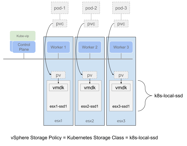
Figure 1.
To setup such an environment, it is necessary to go over some of the requirements first.
Deploy Tanzu Kubernetes Clusters to Multiple Availability Zones on vSphere – link
Spread Nodes Across Multiple Hosts in a Single Compute Cluster
Configure Tanzu Kubernetes Plans and Clusters with an overlay that is topology-aware – link
Deploy TKG clusters into a multi-AZ topology
Deploy the k8s-local-ssd storage class
Deploy Workloads with WaitForFirstConsumer Mode in Topology-Aware Environment – link
Before you start
Note that only the CSI driver for vSphere version 2.4.1 supports local storage topology in a multi-AZ topology. To check if you have the correct version in your TKG cluster, run the following.
tanzu package installed get vsphere-csi -n tkg-system
- Retrieving installation details for vsphere-csi... I0224 19:20:29.397702  317993 request.go:665] Waited for 1.03368201s due to client-side throttling, not priority and fairness, request: GET:https://172.16.3.94:6443/apis/secretgen.k14s.io/v1alpha1?timeout=32s
\ Retrieving installation details for vsphere-csi...
NAME:                    vsphere-csi
PACKAGE-NAME:            vsphere-csi.tanzu.vmware.com
PACKAGE-VERSION:         2.4.1+vmware.1-tkg.1
STATUS:                  Reconcile succeeded
CONDITIONS:              [{ReconcileSucceeded True  }]
Deploy Tanzu Kubernetes Clusters to Multiple Availibility Zones on vSphere
In my example, I am using the Spread Nodes Across Multiple Hosts in a Single Compute Cluster example, each ESXi host is an availability zone (AZ) and the vSphere cluster is the Region.
Figure 1. shows a TKG cluster with three worker nodes, each node is running on a separate ESXi host. Each ESXi host has a local SSD drive formatted with VMFS 6. The topology aware volume provisioner would always place pods and their replicas on separate worker nodes and also any persistent volume claims (PVC) on separate ESXi hosts.
*Note that “cluster” is the name of my vSphere cluster.
Ensure that you’ve set up the correct rules that enforce worker nodes to their respective ESXi hosts. Always use “Must run on hosts in group“, this is very important for local storage topology to work. This is because the worker nodes will be labelled for topology awareness, and if a worker node is vMotion’d accidentally then the CSI driver will not be able to bind the PVC to the worker node.
Below is my vsphere-zones.yaml file.
Note that autoConfigure is set to true. Which means that you do not have to tag the cluster or the ESX hosts yourself, you would only need to setup up the affinity rules under Cluster, Configure, VM/Host Groups and VM/Host Rules. The setting autoConfigure: true, would then make CAPV automatically configure the tags and tag categories for you.
Note that Kubernetes does not like using parameter names that are not standard, I suggest for your vmGroupName and hostGroupName parameters, use lowercase and dashes instead of periods. For example host-group-3, instead of Host.Group.3. The latter will be rejected.
Configure Tanzu Kubernetes Plans and Clusters with an overlay that is topology-aware
To ensure that this topology can be built by TKG, we first need to create a TKG cluster plan overlay that tells Tanzu how what to do when creating worker nodes in a multi-availability zone topology.
Lets take a look at my az-overlay.yaml file.
Since I have three AZs, I need to create an overlay file that includes the cluster plan for all three AZs.
To deploy a TKG cluster that spreads its worker nodes over multiple AZs, we need to add some key value pairs into the cluster config file.
Below is an example for my cluster config file – tkg-hugo.yaml.
The new key value pairs are described in the table below.
Parameter
Specification
Details
VSPHERE_REGION
k8s-region
Must be the same as the configuration in the vsphere-zones.yaml file
VSPHERE_ZONE
k8s-zone
Must be the same as the configuration in the vsphere-zones.yaml file
VSPHERE_AZ_0 VSPHERE_AZ_1 VSPHERE_AZ_2
az-1 az-2 az-3
Must be the same as the configuration in the vsphere-zones.yaml file
WORKER_MACHINE_COUNT
3
This is the number of worker nodes for the cluster.
The total number of workers are distributed in a round-robin fashion across the number of AZs specified.
A note on WORKER_MACHINE_COUNT when using CLUSTER_PLAN: dev instead of prod.
If you change the az-overlay.yaml @ if data.values.CLUSTER_PLAN == “prod” to @ if data.values.CLUSTER_PLAN == “dev”
Then the WORKER_MACHINE_COUNT reverts to the number of workers for each AZ. So if you set this number to 3, in a three AZ topology, you would end up with a TKG cluster with nine workers!
Note that parameters.storagePolicyName: k8s-local-ssd, which is the same as the name of the storage policy for the local storage. All three of the local VMFS datastores that are backed by the local SSD drives are members of this storage policy.
Note that the volumeBindingMode is set to WaitForFirstConsumer.
Instead of creating a volume immediately, the WaitForFirstConsumer setting instructs the volume provisioner to wait until a pod using the associated PVC runs through scheduling. In contrast with the Immediate volume binding mode, when the WaitForFirstConsumer setting is used, the Kubernetes scheduler drives the decision of which failure domain to use for volume provisioning using the pod policies.
This guarantees the pod at its volume is always on the same AZ (ESXi host).
Deploy a workload that uses Topology Aware Volume Provisioning
Below is a statefulset that deploys three pods running nginx. It configures two persistent volumes, one for www and another for log. Both of these volumes are going to be provisioned onto the same ESXi host where the pod is running. The statefulset also runs an initContainer that will download a simple html file from my repo and copy it to the www mount point (/user/share/nginx/html).
You can see under spec.affinity.nodeAffinity how the statefulset uses the topology.
The statefulset then exposes the nginx app using the nginx-service which uses the Gateway API, that I wrote about in a previous blog post.
What if you wanted to use more than three availability zones?
Some notes here on what I experienced during my testing.
The TKG cluster config has the following three lines to specify the names of the AZs that you want to use which will be passed onto the Tanzu CLI to use to deploy your TKG cluster using the ytt overlay file. However, the Tanzu CLI only supports a total of three AZs.
If you wanted to use more than three AZs, then you would have to remove these three lines from the TKG cluster config and change the ytt overlay to not use the VSPHERE_AZ_# variables but to hard code the AZs into the ytt overlay file instead.
To do this replace the following:
      #@ if data.values.VSPHERE_AZ_2:
      failureDomain: #@ data.values.VSPHERE_AZ_0
      #@ end
with the following:
failureDomain: az-2
and create an additional block of MachineDeployment and KubeadmConfigTemplate for each additional AZ that you need.
Summary
Below are screenshots and the resulting deployed objects after running kubectl apply -f to the above.
kubectl get nodes
NAME                             STATUS   ROLES                  AGE     VERSION
tkg-hugo-md-0-7d455b7488-d6jrl   Ready    <none>                 3h23m   v1.22.5+vmware.1
tkg-hugo-md-1-bc76659f7-cntn4    Ready    <none>                 3h23m   v1.22.5+vmware.1
tkg-hugo-md-2-6bb75968c4-mnrk5   Ready    <none>                 3h23m   v1.22.5+vmware.1
You can see that the worker nodes are distributed across the ESXi hosts as per our vsphere-zones.yaml and also our az-overlay.yaml files.
kubectl get po -o wide
NAME    READY   STATUS    RESTARTS   AGE     IP                NODE                             NOMINATED NODE   READINESS GATES
web-0   1/1     Running   0          3h14m   100.124.232.195   tkg-hugo-md-2-6bb75968c4-mnrk5   <none>           <none>
web-1   1/1     Running   0          3h13m   100.122.148.67    tkg-hugo-md-1-bc76659f7-cntn4    <none>           <none>
web-2   1/1     Running   0          3h12m   100.108.145.68    tkg-hugo-md-0-7d455b7488-d6jrl   <none>           <none>
You can see that each pod is placed on a separate worker node.
kubectl get csinodes -o jsonpath='{range .items[*]}{.metadata.name} {.spec}{"\n"}{end}'